Unlock instant, AI-driven research and patent intelligence for your innovation.

Digital Attenuator Circuits and Methods for Use thereof

a digital attenuator and circuit technology, applied in the field of digital controllable attenuator circuits, can solve the problems of pin-diode attenuators that cannot be built on semiconductor chips, easy distortion of the approach,

Inactive Publication Date: 2011-02-03
CSR TECH INC
View PDF53 Cites 1 Cited by
  • Summary
  • Abstract
  • Description
  • Claims
  • Application Information

AI Technical Summary

Benefits of technology

[0009]An advantage of one or more embodiments is that the attenuator circuit can be implemented in a chip along with various other components of a tuner. In fact, one or more of such attenuator circuits can be placed along the RF signal path, including before the first amplifier. In such manner, attenuation can be performed on large input signals so that the actual signal level going into the first amplifier is at or below a “take over point,” or other reference level.

Problems solved by technology

However, this approach is prone to distortion, since the AGC is performed inside the amplifier.
However, pin-diode attenuators typically cannot be built on a semiconductor chip, such that in tuner-on-chip applications, the attenuation is performed off-chip.

Method used


Image

  • Digital Attenuator Circuits and Methods for Use thereof
  • Digital Attenuator Circuits and Methods for Use thereof
  • Digital Attenuator Circuits and Methods for Use thereof

Examples


Embodiment Construction

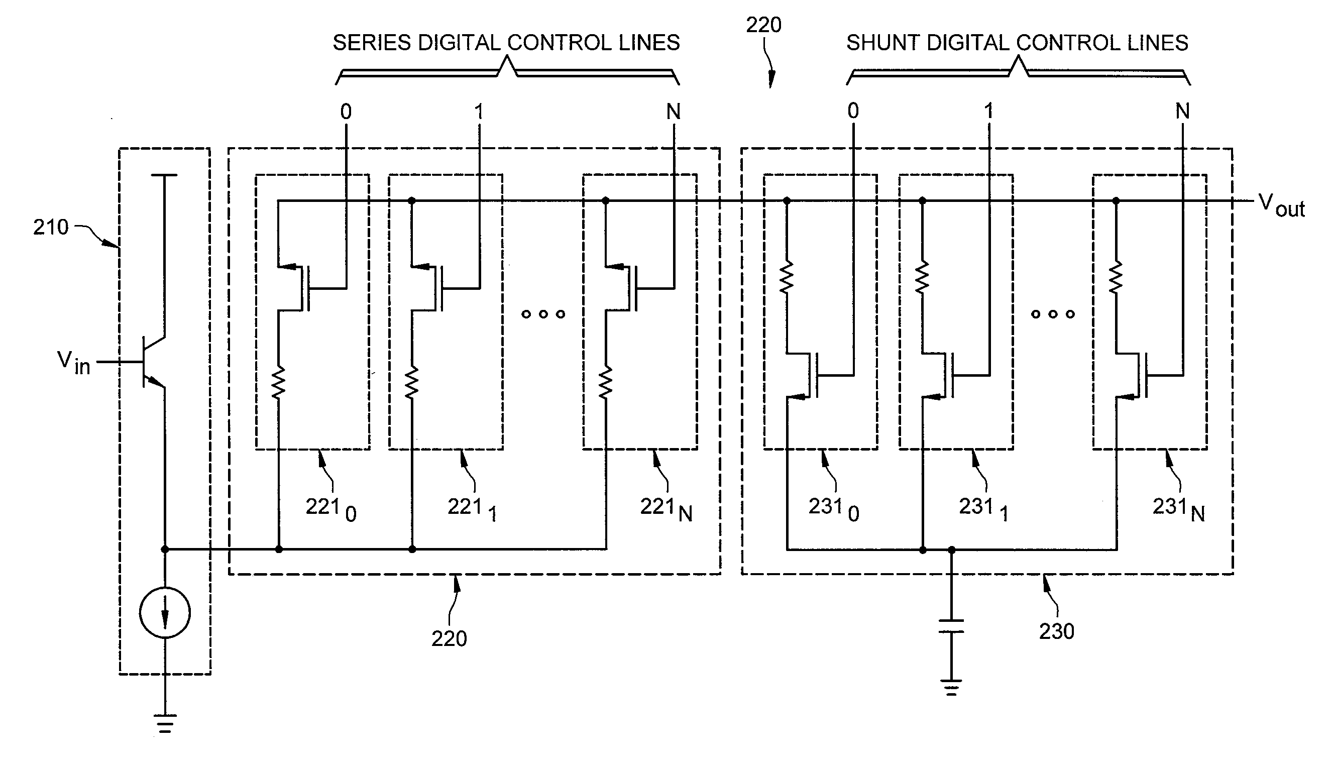
[0021]FIG. 1 is an illustration of exemplary system 100 adapted according to one embodiment of the invention. System 100 includes input component 110 receiving an input signal that has a voltage Vin, first adjustable impedance component 120, and second adjustable impedance component 130, which is shunted to ground. Output voltage Vout, at output component 140 (e.g., wire, contact, or the like), is fed to the input of circuit component 150 (e.g., amplifier, mixer, filter, or the like). First adjustable impedance component 120 may be referred to herein as a “series” component because it is in series in first current path 160 between input component 110 and output component 140. Likewise, second adjustable impedance component 130 may be referred to herein as a “shunt” component because it is shunted. Second adjustable impedance component 130 creates second current path 170.

[0022]Each of first and second adjustable impedance components 120 and 130 includes a plurality of selectable, dis...


PUM


Abstract

An attenuator system includes a first adjustable impedance component on a first current path between a input component and a output component, and a second adjustable impedance component between the first current path and ground, wherein each of the first and second adjustable impedance components include a plurality of selectable, discrete legs, each leg having an impedance.

Description

CROSS-REFERENCE TO RELATED APPLICATIONS[0001]This application is a continuation-in-part of U.S. patent application Ser. No. 12 / 352,430 filed Jan. 12, 2009 and entitled, “AGC METHOD USING DIGITAL GAIN CONTROL,” which is a continuation of U.S. patent application Ser. No. 11 / 442,643 filed May 26, 2006 and entitled “DIGITAL ATTENUATOR CIRCUITS AND METHODS FOR USE THEREOF,” the disclosures of which are hereby incorporated herein by reference.[0002]The present application is also related to co-pending and commonly-assigned U.S. patent application Ser. No. 11 / 441,816 filed May 26, 2006, entitled, “AGC SYSTEM AND METHOD FOR BROADBAND TUNERS,” the disclosure of which is hereby incorporated herein by reference.TECHNICAL FIELD[0003]The present description relates, in general, to attenuator circuits, and more specifically, to digitally-controllable attenuator circuits.BACKGROUND OF THE INVENTION[0004]In prior art Radio Frequency (RF) tuners, Automatic Gain Control (AGC) is often performed at th...

Claims


Application Information

Patent Timeline
Patent Type & Authority Applications(United States)
IPC IPC(8): H03L5/00
CPCH03G1/0088H03H7/25H03G3/001
Inventor STEVENSON, JAN-MICHAEL
Owner CSR TECH INC
Features
  • R&D
  • Intellectual Property
  • Life Sciences
  • Materials
  • Tech Scout
  • Unparalleled Data Quality
  • Higher Quality Content
  • 60% Fewer Hallucinations
Learn More