Time of Flight Camera with Rectangular Field of Illumination

a technology of time-of-flight camera and rectangular field, which is applied in the field of time-of-flight camera with rectangular field of illumination, can solve the problems of inability to achieve the effect of reducing the cost of customizing a micro-optical design, limited commercial availability of different emission angles, and inability to achieve the effect of economic benefits

Active Publication Date: 2011-02-03
AMS SENSORS SINGAPORE PTE LTD
View PDF13 Cites 84 Cited by
  • Summary
  • Abstract
  • Description
  • Claims
  • Application Information

AI Technical Summary

Problems solved by technology

Because the commercial availability of different emission angles is limited and in most cases they do not fit the specifications of the camera's FOV, one has to start designing customized optics for the illumination.
However, customizing a micro-optical design is costly and in most cases not practical in an economical sense.
For that reason, most 3D camera manufacturer use non-optimized micro-optics on the light sources.

Method used


Image

  • Time of Flight Camera with Rectangular Field of Illumination
  • Time of Flight Camera with Rectangular Field of Illumination
  • Time of Flight Camera with Rectangular Field of Illumination

Examples


Embodiment Construction

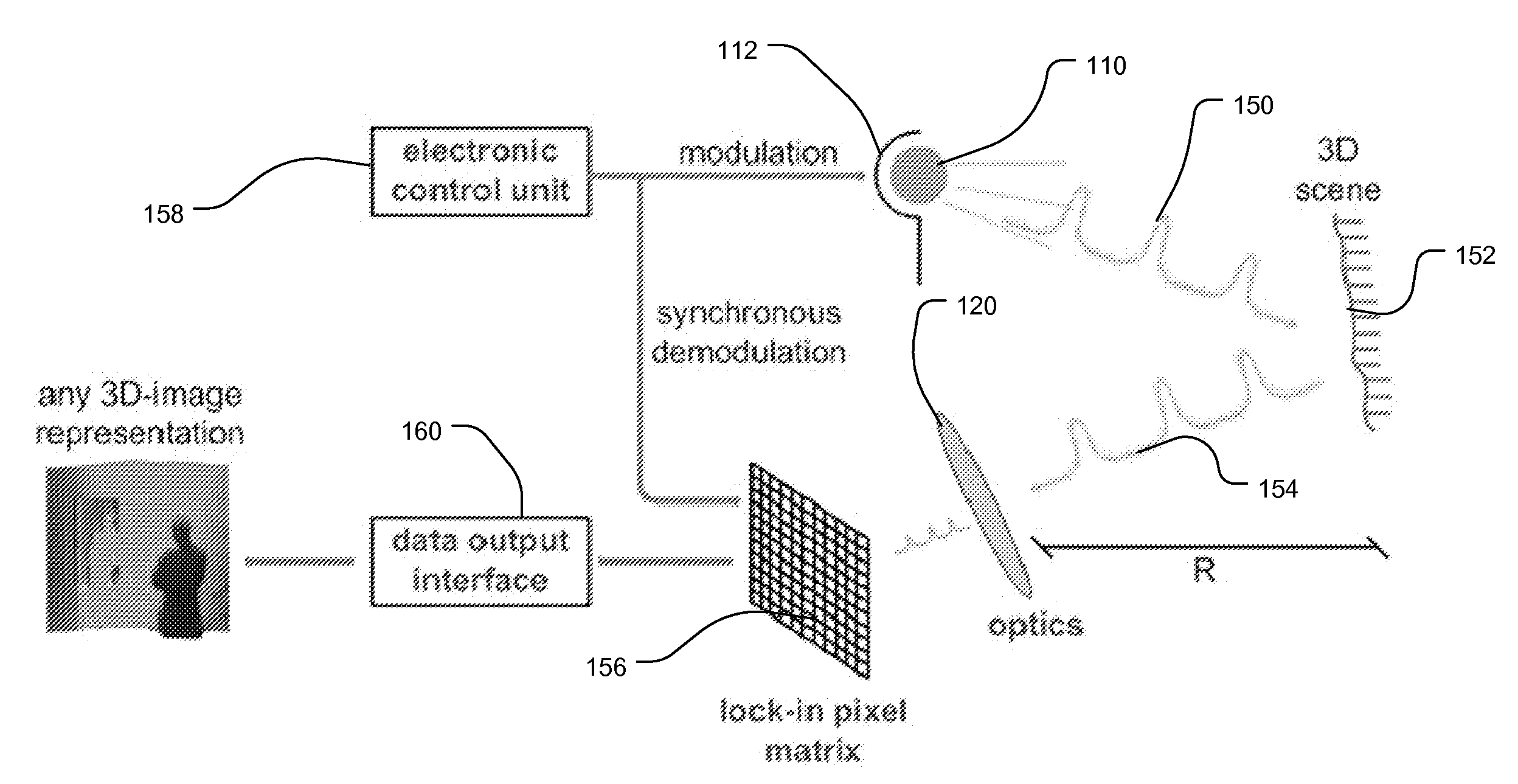
[0026]FIG. 3 shows a light source 100 for a TOF camera according to the principles of the present invention.

[0027]A light emitter 110 is positioned in a rectangular reflector 112 that is formed in a frame 114.

[0028]In the current embodiment, the light emitter 110 is an LED or laser diode. The reflector 112 comprises four angled triangular surfaces a, b, c, d of the substrate 114 that angle in obliquely toward the light emitter 110 to form a frusto pyramidal cut-out in the substrate 114. In this embodiment, the reflector 112 has a rectangular cross section. In the preferred embodiment, the surfaces a, b, c, d of the frusto pyramidal reflector 112 are coated to be reflective such as with a metal coating to direct light from the light emitter onto a scene of interest.

[0029]FIG. 4 is cross section of a ray tracing using the example of an LED light emitter 110 with the square-shaped reflector 112 formed in the substrate 114.

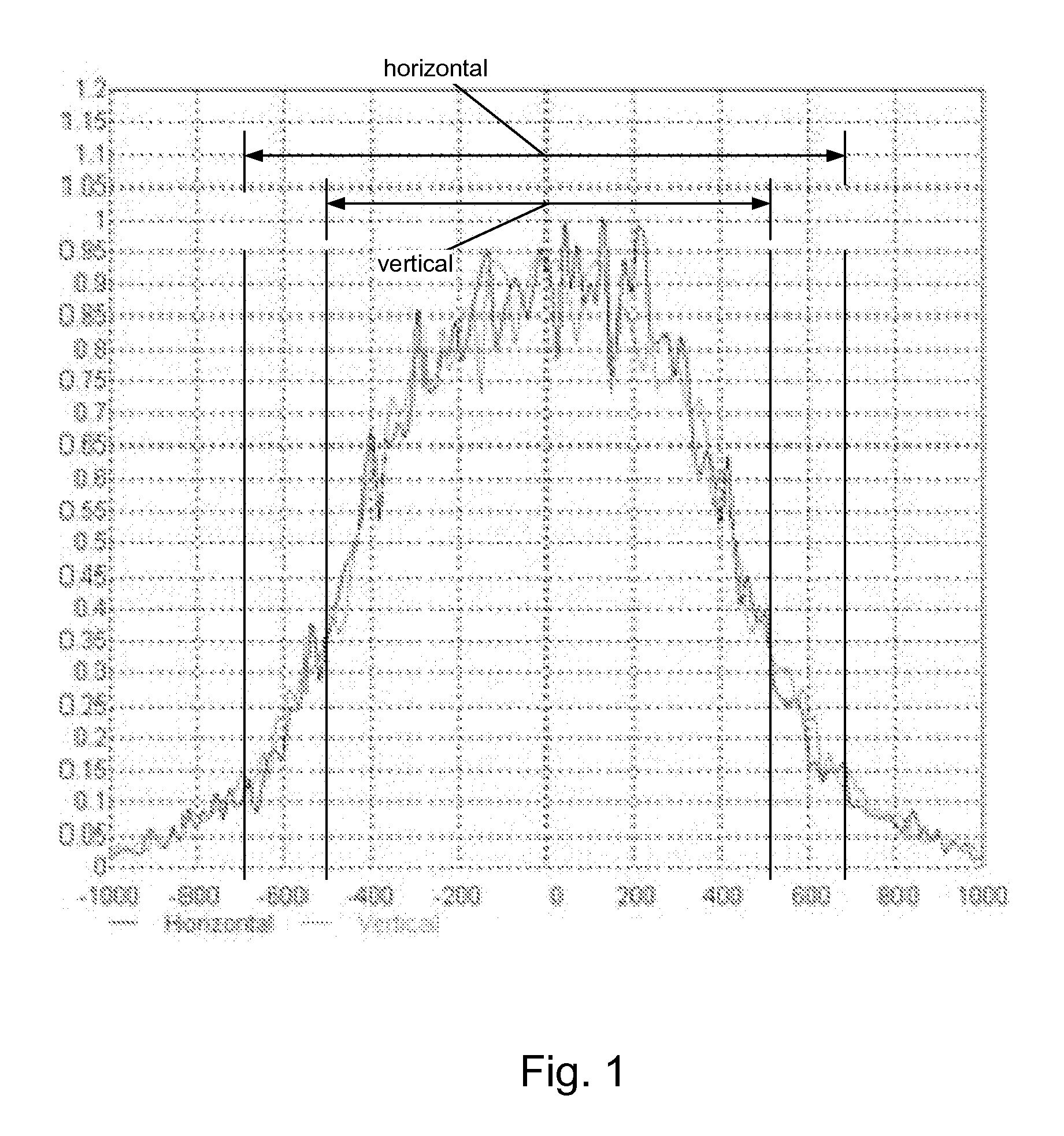
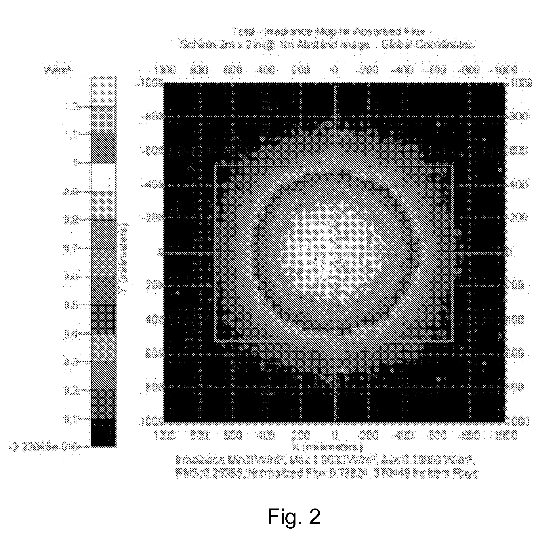
[0030]FIGS. 5 and 6 show a simulation of the far field intensity...


PUM


Abstract

Improved field-of-illumination (FOI) and field-of-view (FOV) matching for 3D time-of-flight cameras is provided using light emitters with rectangular reflectors. A better adjustment of the FOI with the camera's FOV has the following advantages: optimal use of emitted light and reduced multi-path problems. Furthermore, embodiments bring the benefit for rather low-cost customization of the illumination to match the FOI to the specified FOV.

Description

RELATED APPLICATIONS[0001]This application claims the benefit under 35 USC 119(e) of U.S. Provisional Application No. 61 / 230,239, filed on Jul. 31, 2009, which is incorporated herein by reference in its entirety.BACKGROUND OF THE INVENTION[0002]Current commercially available three-dimensional (3D) time of flight (TOF) cameras use in general an array of light emitting diodes (LEDs) with micro-lenses that more or less have a similar field of illumination (FOI) as the field of view (FOV) covered by the camera. Laser-based 3D TOF cameras also require a specific micro-optical design to generate a FOI that matches to the FOV of the camera.[0003]LEDs are commercially available as surface-mount devices. They can be ordered either without any micro-lens or with micro-lens. A micro-lens is required for narrower emission angles. With respect of 3D sensing, such devices have two main drawbacks:[0004]In general, the emission field has circular shape. On the other side, the imaged area on the ima...

Claims


Application Information

Patent Timeline
Patent Type & Authority Applications(United States)
IPC IPC(8): H04N7/18G01S17/894G01S17/931
CPCG01S7/4814G01S17/936G02B19/0019H04N13/0203G02B19/0061G02B5/09H04N5/2256G02B19/0052H04N13/204G01S17/931G01S17/894H04N23/56
Inventor OGGIER, THIERRYRICHTER, MICHAEL
Owner AMS SENSORS SINGAPORE PTE LTD
Why Eureka
Try Eureka