Adaptive neighborhood filtering (ANF) system and method for 3D time of flight cameras

a technology of neighborhood filtering and flight cameras, applied in the field of adaptive neighborhood filtering (anf) system and method for 3d time flight cameras, can solve the problems of reducing the performance of such demodulation pixels, difficult to realize high frequencies when many pixels are controlled, and poor fill-factor of like structures

Active Publication Date: 2012-07-17
AMS SENSORS SINGAPORE PTE LTD
View PDF9 Cites 26 Cited by
  • Summary
  • Abstract
  • Description
  • Claims
  • Application Information

AI Technical Summary

Problems solved by technology

Nevertheless, the stripe-like structure leads to a poor fill-factor because the regions between the stripes are not photo-sensitive.
Here, any delay of the sampling signal arising on the photo-gate due to large resistance-capacitance (RC) times can reduce the performance of such demodulation pixels.
In particular, high frequencies are difficult to realize when many pixels are controlled at the same time.

Method used


Image

  • Adaptive neighborhood filtering (ANF) system and method for 3D time of flight cameras
  • Adaptive neighborhood filtering (ANF) system and method for 3D time of flight cameras
  • Adaptive neighborhood filtering (ANF) system and method for 3D time of flight cameras

Examples


first embodiment

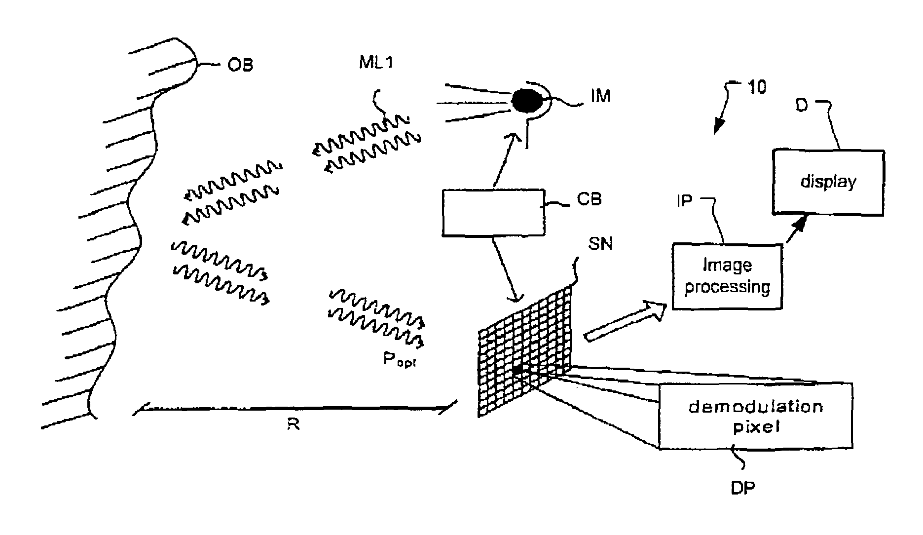
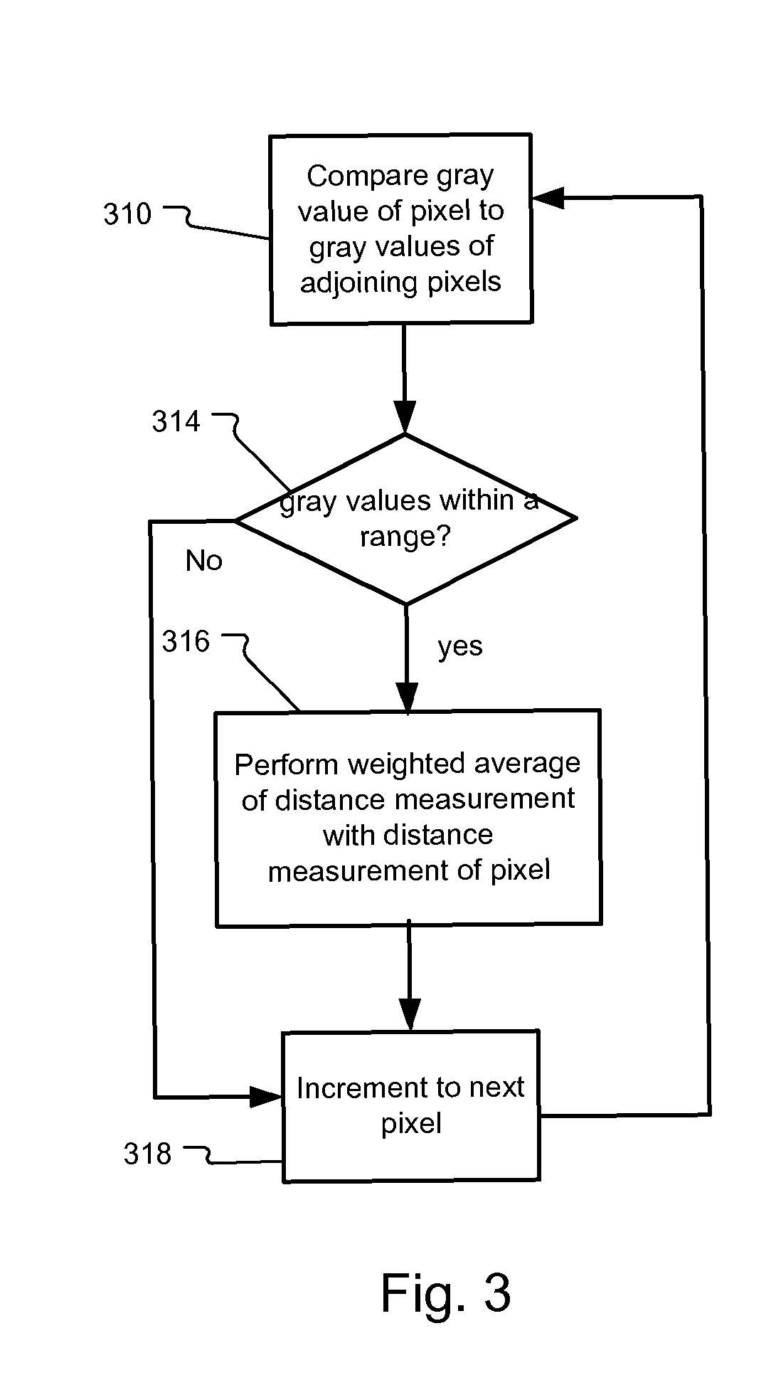
[0031]FIG. 3 illustrates the ANF in which the image processor IP steps through the responses of the demodulation pixels DP of the image sensor SN. If the neighboring pixels have similar amplitude or gray values, the probability that the pixels are in the same plane is deemed high. Hence, such pixels are spatially averaged in distance information with higher weight.

[0032]In more detail, the image processor compares the gray or amplitude value of a pixel to the gray or amplitude values of adjoining and / or adjacent pixels, in step 310. The pixels are characterized by a two dimensional array of n by m pixels in the image sensor. In one example, the processing begins with pixel (x0,y0) and ends with pixel (xn,ym).

[0033]It determines whether any of the gray values of the adjacent pixels are within a range around the gray value of the current pixel in step 314. In one example the gray value of pixel (xa,yb) is compared to the gray values of pixels (xa+1,yb), (xa−1,yb), (xa,yb+1), and (xa,y...

second embodiment

[0035]FIG. 4 illustrates the ANF in which the image processor IP steps through the responses of the demodulation pixels DP of the image sensor SN. If the neighboring pixels have similar distance values, the probability that the pixels are in the same plane is rather high. Hence, such pixels are spatially averaged with higher weight.

[0036]In more detail, the image processor compares the distance value of a pixel to the distance values of adjoining and / or adjacent pixels, in step 410. In one example the distance value of pixel (xa,yb) is compared to the distance values of pixels (xa+1,yb), (xa−1,yb), (xa,yb+1), and (xa,yb−1).

[0037]It determines whether any of the distance values of the adjacent pixels are within a range around the depth value of the current pixel in step 414. The distance information is averaged with the adjacent pixels that are within the range in step 416. Usually the average is weighted average here also. The range is selected in response to the gray value of the p...


PUM


Abstract

A method for filtering distance information from a 3D-measurement camera system comprises comparing amplitude and / or distance information for pixels to adjacent pixels and averaging distance information for the pixels with the adjacent pixels when amplitude and / or distance information for the pixels is within a range of the amplitudes and / or distances for the adjacent pixels. In addition to that the range of distances may or may not be defined as a function depending on the amplitudes.

Description

RELATED APPLICATIONS[0001]This application claims the benefit under 35 USC 119(e) of U.S. Provisional Application No. 61 / 024,614, filed on Jan. 30, 2008, which is incorporated herein by reference in its entirety.BACKGROUND OF THE INVENTION[0002]Time of flight (TOF) sensors typically utilize charge-coupled device (CCD) or complementary metal oxide semiconductor (CMOS) based technologies that are able to sample at high speed. The typical application is for point distance sensing or three-dimensional (3D) imaging in which the scene of interest is actively illuminated with modulated illuminating radiation and the sensor sampling is performed synchronously with the modulation of the illuminating radiation. These high speed sensors are also useful in other applications such as fluorescence lifetime imaging.[0003]Generally, in these sensors, light is converted to electrical charge carriers in the form of electron-hole pairs in a photosensitive region. Usually electrons, but also holes, are...

Claims


Application Information

Patent Timeline
Patent Type & Authority Patents(United States)
IPC IPC(8): H04N5/228G01S17/894G06T5/50H04N5/217H04N5/369
CPCG01S17/89G06T7/0065G06T5/002G06T7/55G01S17/894
Inventor OGGIER, THIERRYBUETTGEN, BERNHARDZAMOFING, THIERRY
Owner AMS SENSORS SINGAPORE PTE LTD
Why Eureka
Try Eureka