Depth calculation imaging method based on flight time TOF camera

A TOF camera and depth calculation technology, applied in the field of computer vision, can solve the problem of low resolution of the camera depth map

Active Publication Date: 2012-09-12
TIANJIN UNIV
View PDF0 Cites 27 Cited by
  • Summary
  • Abstract
  • Description
  • Claims
  • Application Information

AI Technical Summary

Problems solved by technology

In order to achieve the above purpose, solve the problem of low resolution of TOF camera depth map

Method used


Image

  • Depth calculation imaging method based on flight time TOF camera
  • Depth calculation imaging method based on flight time TOF camera
  • Depth calculation imaging method based on flight time TOF camera

Examples


Embodiment Construction

[0041] The method for optimizing the depth map of the TOF depth camera using the autoregressive model with guidance of the present invention will be described in detail below in conjunction with the embodiments and the accompanying drawings.

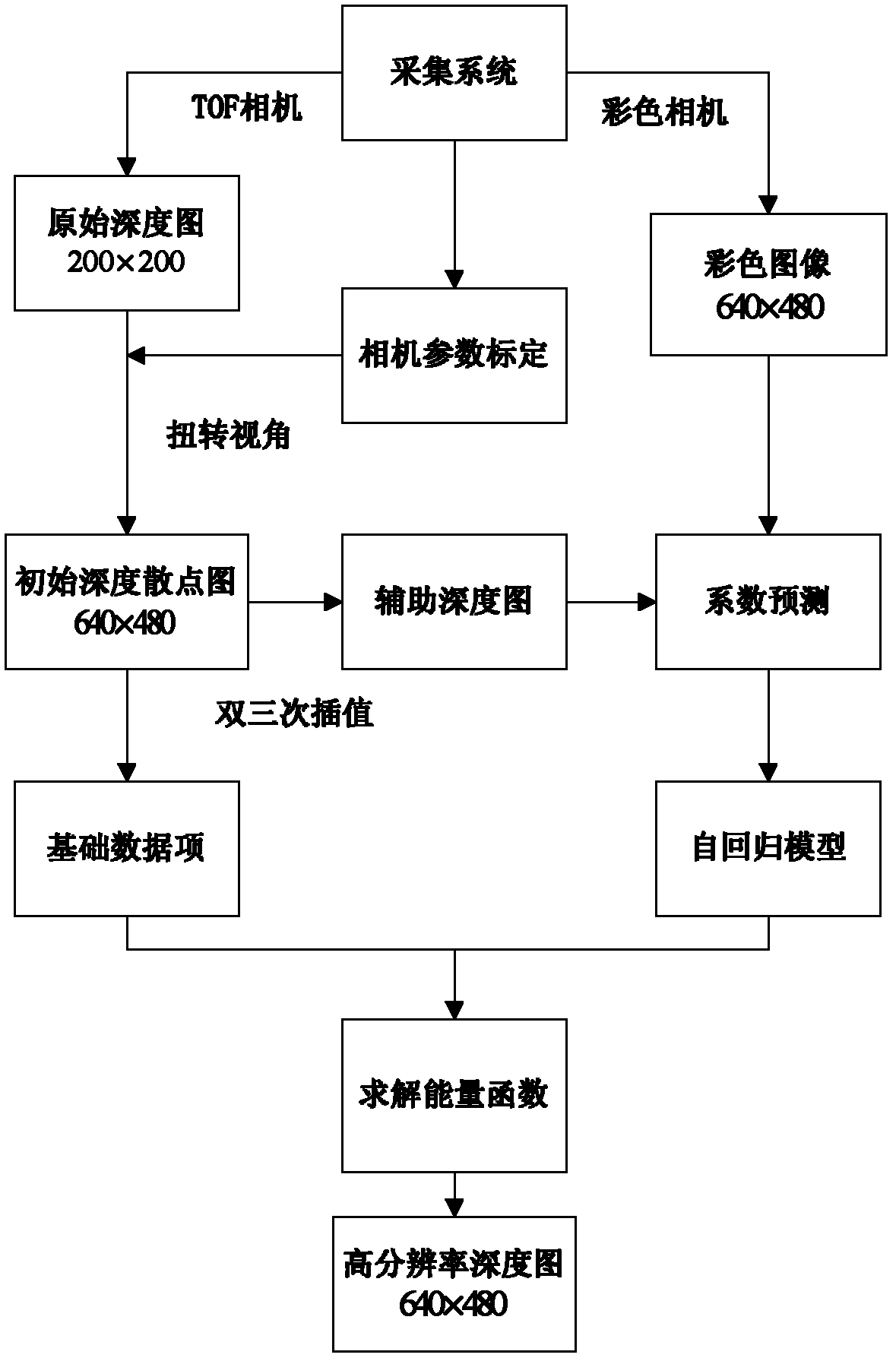
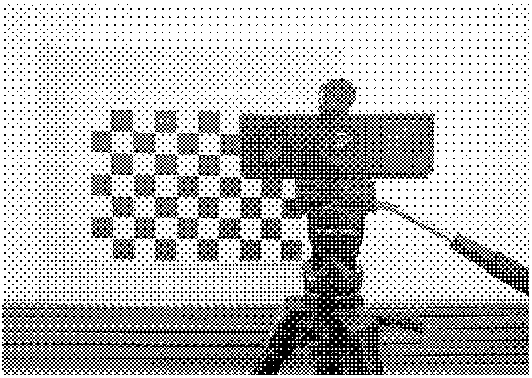
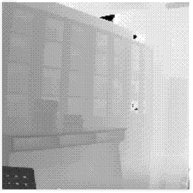
[0042] In order to solve the problem of low resolution of TOF camera depth map, a simple and practical post-processing method is provided. The device of the present invention is equipped with: a TOF PMD[vision]camcube3.0 camera, and a Point Gray Flea2 color camera; the system is formed by placing the color camera above the TOF camera. The technical scheme adopted by the present invention is to use the autoregressive model to perform super-resolution reconstruction on the depth map: the depth map super-resolution problem is specifically expressed as an autoregressive model solution equation, and through 1) using the method of bilateral filtering in the aligned color The image performs color-guided coefficient training on the autoregressive ...


PUM


Abstract

The invention belongs to the field of computer vision. In order to achieve the balance between general quantization error and overload error to ensure that the quantization output noise-signal ratio is optimum, the method adopts the technical scheme of a depth calculation imaging method based on a flight time TOF camera, and the method comprises the following steps: firstly, obtaining respective internal parameters including focal distances and optical centers and external parameters including rotation and translation of the TOF camera and a color camera after camera calibration, and obtaining a plurality of depth scatters on a high resolution diagram; secondly, building an autoregression model item of an energy function; thirdly, building an basic data item and a final solve equation of the energy function, building a data item of the energy function through an initial depth scatter diagram, and combining the data item and an autoregression item with a factor Lambada into a whole body to be served as a final solve equation through a lagrange equation; and fourthly, performing solving on an optimized equation through a linear function optimization method. The method is mainly applied to digital image processing.

Description

technical field [0001] The invention belongs to the field of computer vision and relates to a method for optimizing a depth map of a TOF depth camera by using an autoregressive model. Specifically, it relates to a depth calculation imaging method based on a time-of-flight TOF camera. Background technique [0002] At present, 3D (three-dimension) scene depth acquisition has become one of the most basic challenges in computer vision. Its applications cover robot navigation, model reconstruction, and human-computer interaction. In previous technologies, people used methods such as laser scanning and stereo matching algorithms to obtain depth information. Unfortunately, these existing depth acquisition methods are not very ideal: for example, laser scanning uses point-by-point scanning, and obtaining depth is too time-consuming, which is not suitable for dynamic scenes; stereo matching will not match in scene areas without texture and occlusion , resulting in an inaccurate de...

Claims


Application Information

Patent Timeline
IPC IPC(8): G06T5/10G06T7/00
Inventor 杨敬钰叶昕辰侯春萍李坤
Owner TIANJIN UNIV
Why Eureka
Try Eureka