
Image forming apparatus, control method therefor, and storage medium storing program for the same

a technology of image forming apparatus and control method, which is applied in the direction of electrographic process, instruments, transportation and packaging, etc., can solve the problems of affecting the operation of the entire apparatus, affecting the efficiency of the whole apparatus, so as to eliminate the user's effort

Inactive Publication Date: 2011-02-03
CANON KK
View PDF2 Cites 12 Cited by
  • Summary
  • Abstract
  • Description
  • Claims
  • Application Information

AI Technical Summary

Benefits of technology

[0014]The present invention provides an image forming apparatus able to eliminate the user's effort to determine the necessity of part replacement and usable over a longest possible time period, and provides a control method for the image forming apparatus and a storage medium storing a program for executing the control method.Solution to Problem

Problems solved by technology

Nevertheless, in a case that maintenance is carried out by a user, the user does not always care about consumption degrees of consumable parts and is liable to overlook the necessity for consumed part replacement.
When a consumed part to be replaced is kept used without replacement, there is a fear that a jam and other trouble are frequently caused.
In that case, if a part in trouble is detected and the usage thereof is simply prohibited, the entire apparatus function or some apparatus function cannot be utilized due to the presence of that one part to be replaced.
As a result, the user's convenience is greatly impaired.
Further, it is difficult for the user to determine whether or not a consumed part not usable will be used for a job which the user wishes to perform.

Method used


Image

  • Image forming apparatus, control method therefor, and storage medium storing program for the same
  • Image forming apparatus, control method therefor, and storage medium storing program for the same
  • Image forming apparatus, control method therefor, and storage medium storing program for the same

Examples


Embodiment Construction

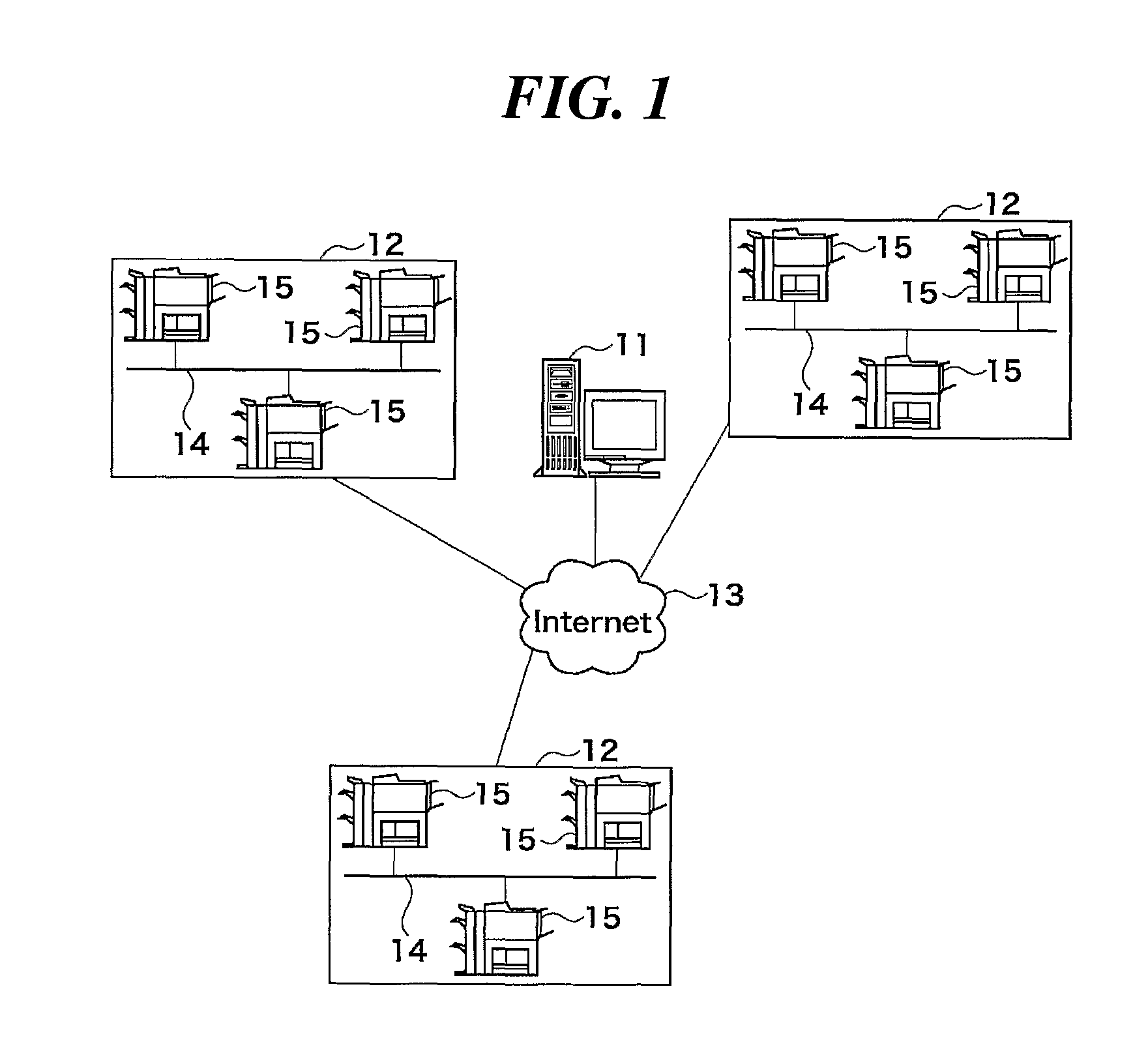
[0031]In the following, a best mode for carrying out this invention will be described with reference to the appended drawings. FIG. 1 shows the system construction of an image forming system including image forming apparatuses according to one embodiment of this invention.

[0032]In the image forming system in FIG. 1, monitoring servers (one of which is shown at 11) and intranets 12 are connected to the internet 13. Each of the intranets 12 has a LAN 14 to which a plurality of image forming apparatuses 15 such as MFPs are connected. The monitoring servers 11 are each disposed at a corresponding one of locations. Each monitor server 11 collectively monitors operation states of image forming apparatuses 15 belonging to one or more intranets 12 assigned to the monitoring server 11.

[0033]Each monitoring server 11 is connected to an intranet (not shown) of a vender of image forming apparatuses 15, and acquires information such as printer engine type, image formation speeds, sheet transfer ...


PUM


Abstract

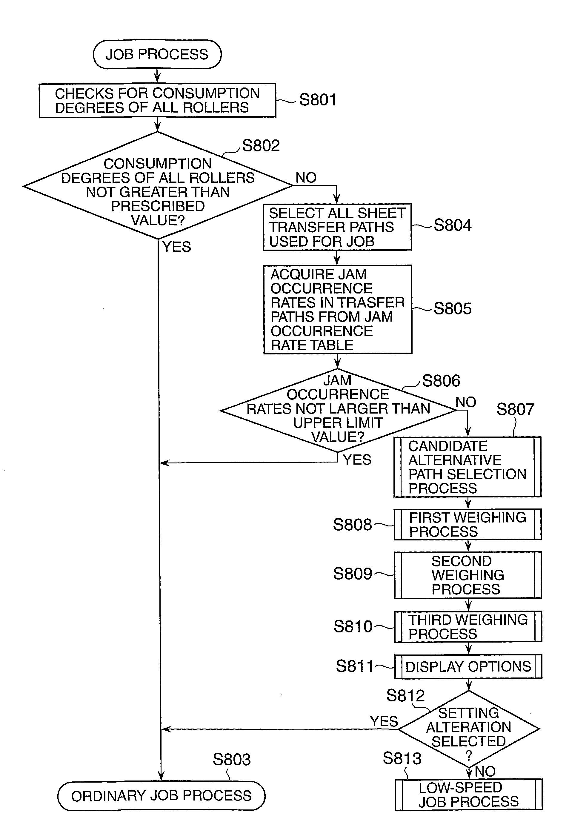
An image forming apparatus capable of being used for a longest possible time period without the need for a user to determine the necessity of part replacement. In a case that a conveyance roller or other part whose consumption degree exceeds a prescribed value is used for a job set by the user, an MFP displays to the user candidates for alternative process using an alternative path in which the conveyance roller or other part is not used and a candidate for alternative process to perform a low-speed process (S702 to S704). The candidates for alternative paths are selected based on weight information set in such a manner that alternative paths are selected in an ascending order of jam occurrence rate acquired from a monitoring server.

Description

TECHNICAL FIELD [0001]The present invention relates to an image forming apparatus, a control method therefor, and a storage medium storing a program for executing the control method. More particularly, this invention relates to a technique to provide a countermeasure against a recording sheet jam.BACKGROUND ART[0002]There have been known an image forming apparatus such as a copier, a printer, or the like having part counters for counting operation amounts of consumable parts and adapted to carry out an optimum image formation based on the counted operation amounts of consumable parts.[0003]For example, some known image forming apparatus is designed to refer to part counters to confirm operation amounts of consumable parts before execution of a job and preferentially use a consumable part having a lowest use frequency among consumable parts associated with an output form desired by a user, to thereby prolong the service life of the entire apparatus (see, PTL (Patent Literature) 1,sho...

Claims


Application Information

Patent Timeline
IPC IPC(8): G06K15/00
CPCB41J11/006G03G15/553B65H29/60B65H2511/529B65H2513/42B65H2513/51B65H2513/52B65H2801/06G03G15/55B41J13/0009G03G15/5079B65H2601/121B65H2515/842B65H2220/01B65H2220/02B65H2220/03B65H2220/11B65H2515/84
Inventor HAMAGUCHI, JUN
Owner CANON KK
Learn More