
Eureka
For R&D, Eureka makes reading and utilizing patents & technical documents easy.
Eureka AIR
Designed for self-driven R&D workflows. Generate viable solutions, solve complex R&D challenges, empower your innovation with AI.

Eureka Materials
Designed for material experts only. Revolutionize your material R&D, from search, analyze, to developing new materials.

TechResearch
Generate reliable direction feasibility study reports for your R&D in just a few steps.

TechSeek
Discover and master advanced knowledge NOW. Basics, ideas, possibilities, all at once.

TechMind
As an expert in R&D Theories, TechMind can generates customized viable solutions instantly.

TechRisk
Analyze your overall solution with one click, know your potential R&D risks in advance.

TechMonitor
Get weekly tech updates, stay abreast of the latest tech innovations and key insights.
Lumbar jack implant
- Summary
- Abstract
- Description
- Claims
- Application Information
AI Technical Summary
Benefits of technology
Problems solved by technology
Method used
Image

Examples
Embodiment Construction
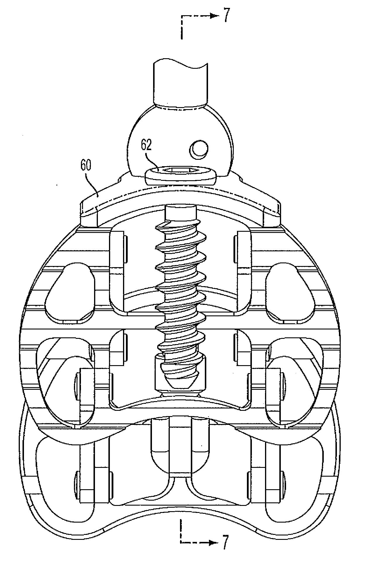
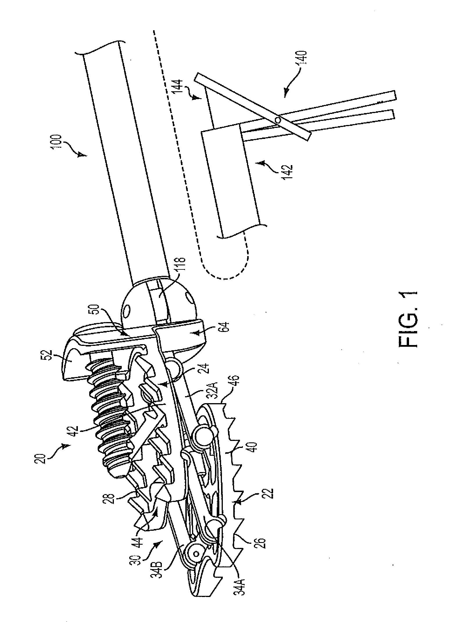
[0021]FIG. 1 shows an implant 20.
[0022]For ease of reference, a frame of reference identifying: upper and lower; left and right; and front and back (including equivalents) is taken relative to an installed condition with the patient standing upright, and the directions being the directions from the point of view of the patient (rather than someone standing in front of the patient and facing the patient).
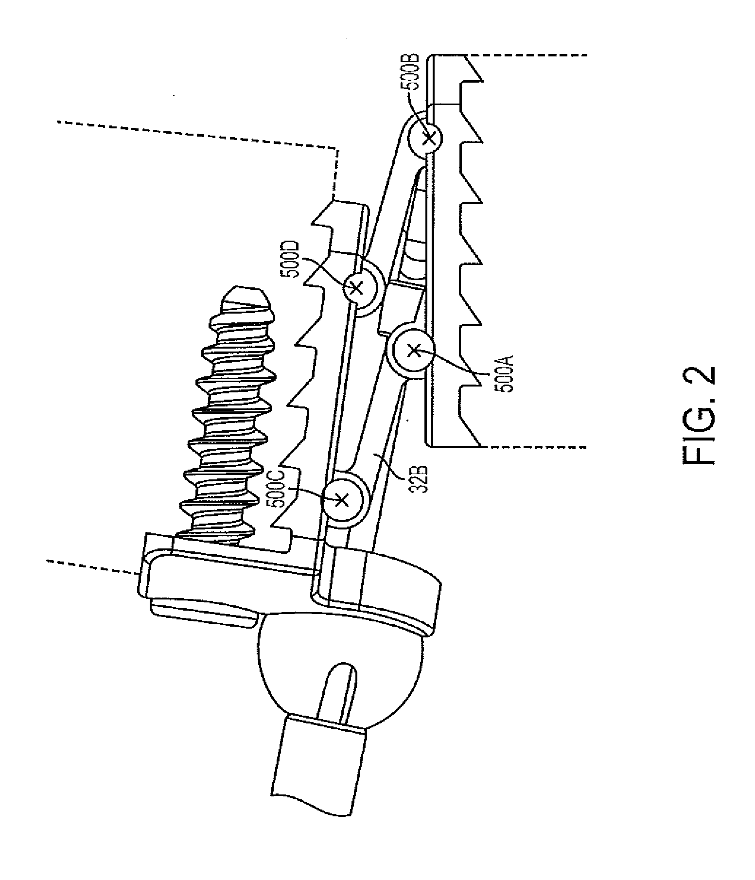
[0023]The exemplary implant 20 has a lower bone-engaging member 22 (a bottom member or base) and an upper bone-engaging 24 (e.g., a top member). As is discussed further, the exemplary members may be articulated between a fully compressed / contracted / closed condition and a fully extended / expanded / opened condition. Insertion / installation may be in a relatively compressed condition (e.g., including the fully compressed condition) with subsequent expansion. The lower member has a bottom surface (underside) 26 for engaging an upper surface of the adjacent bone below (e.g., the sacrum). The...
PUM
 Abstract
Description
Claims
Application Information
 - R&D Engineer
- R&D Manager
- IP Professional
- Industry Leading Data Capabilities
- Powerful AI technology
- Patent DNA Extraction
Browse by: Latest US Patents, China's latest patents, Technical Efficacy Thesaurus, Application Domain, Technology Topic, Popular Technical Reports.
© 2024 PatSnap. All rights reserved.Legal|Privacy policy|Modern Slavery Act Transparency Statement|Sitemap|About US| Contact US: help@patsnap.com