
Robotic platform & methods for overcoming obstacles

a robotic platform and obstacle technology, applied in the direction of end-of-track vehicles, transportation and packaging, vehicles, etc., can solve the problems of not being able to meet the needs of operation, requiring quite bulky remote control units, and adding another level of complexity to the task

Inactive Publication Date: 2011-02-10
DEFENSE VISION
View PDF11 Cites 11 Cited by
  • Summary
  • Abstract
  • Description
  • Claims
  • Application Information

AI Technical Summary

Benefits of technology

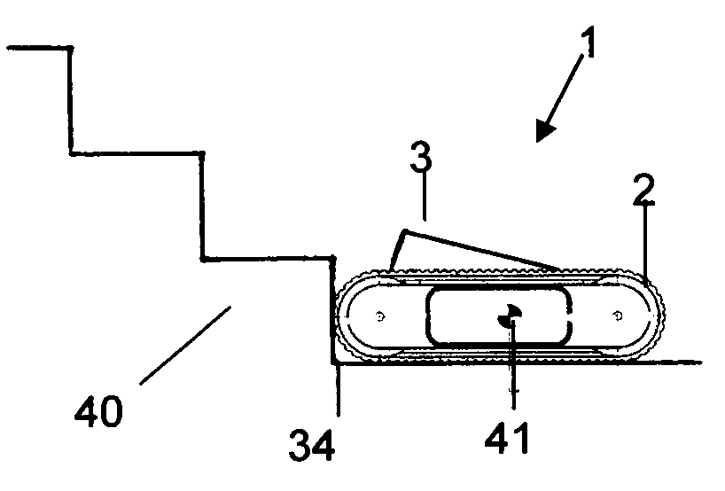
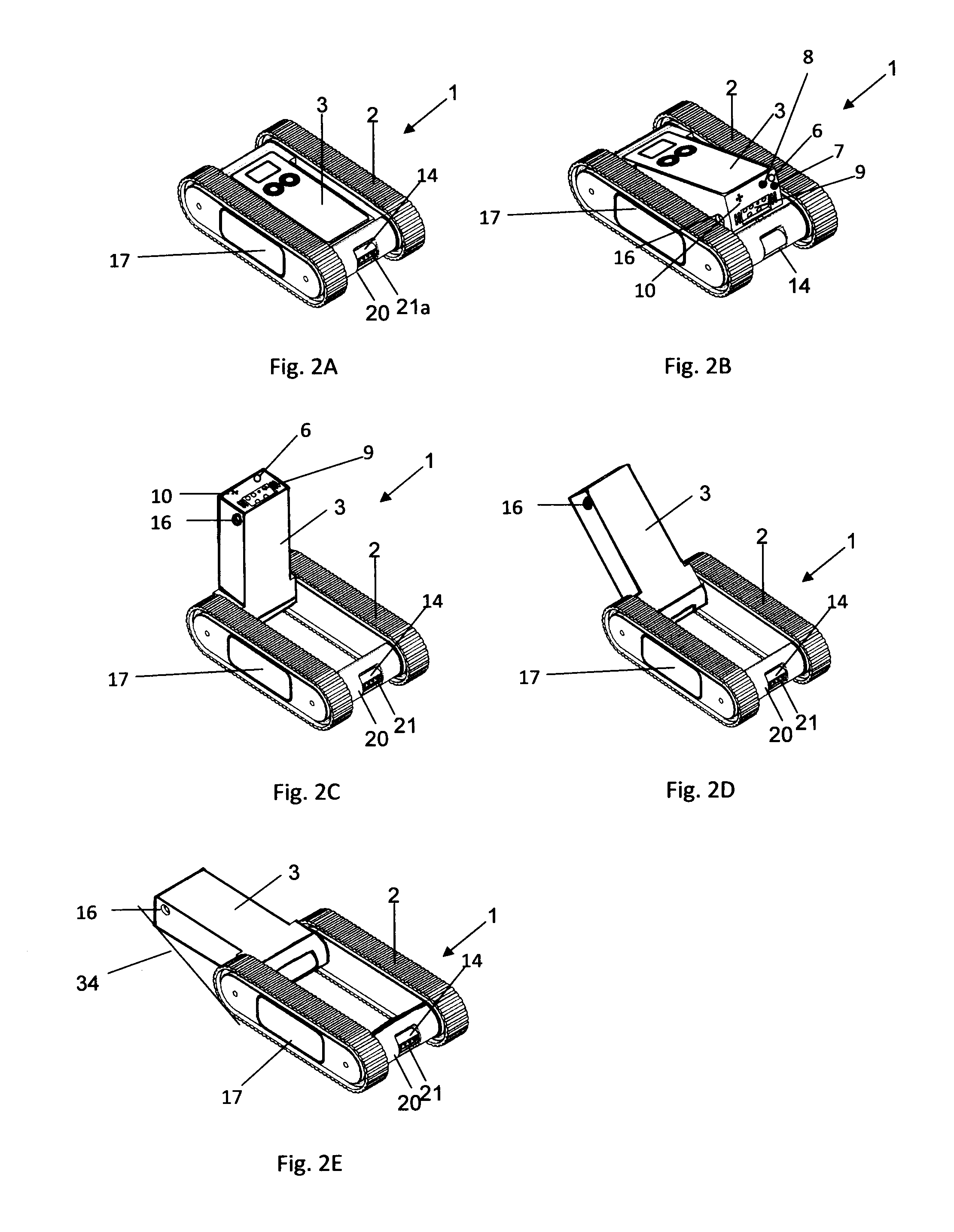
[0034]In an embodiment of a robotic platform the operational assembly may facilitate overcoming and obstacle by shifting the center of gravity of the robotic platform away from the obstacle. The shifting of the center of gravity may assist in raising of an near end of the robotic platform (the near end being the end that is near the obstacle) over the obstacle.
[0036]In an embodiment of a robotic platform the operational assembly may facilitate overcoming and obstacle a power supply of the robotic platform may be mounted to the operational assembly. Mounting the power supply to the operational assembly may cause moving of the power supply when the operational assembly changes angel and because the power supply is heavy, this may cause a large change in the location of the center of mass of the robotic platform.
[0058]An embodiment of a method of overcoming an obstacle with a robotic platform may include raising a near end (the near end being the end that is near the obstacle) of the robotic platform over the obstacle, and shifting the center of gravity of the robotic platform in the direction of travel thereby facilitating raising of a far end of the robotic platform (the far end being the end that is far from the obstacle).

Problems solved by technology

One major challenge in the field of robotics is mobility, in other words, the ability to drive a robotic platform from one point to another.
Another level of complexity is added to this task when the control over the platform is to be maintained during changing environmental conditions such as darkness, harsh weather, etc.
A common obstacle that a robotic platform may need to overcome is stairs.
Another major challenge in the field of robotics is synchronization, in other words, the ability to coordinate between different components integrated into a robotic platform in a manner which facilitates controlling the robotic platform by a remote operator.
In addition, this requires quite bulky remote-control units which are not adequate for operational needs.
Another level of complexity is added to this synchronization of the three factors described above when synchronization is to be maintained when the robotic platform is in motion or when some of the components described above need to be traversed or tilted towards targets in the surroundings of the robotic platform.
The main drawbacks of such a mechanism and the Flipping Maneuver from an operational point of view are (i) the need to perform the Flipping Maneuver when the platform lands on its back side simply delays the platform's operation, (ii) the Flipping Maneuver mechanism is vulnerable during deployment due to the elongated arm which extends out of the secured main frame, (iii) the need to perform the Flipping Maneuver may jeopardize the operation of the platform when it lands near obstacles which might prevent performing the Flipping Maneuver and (iv) the elongated arms associated with the platform increase the overall volume of the platform and therefore decrease its mobility in condensed environments such as tunnels, earthquake wrecks, buildings, etc.
Michaud does not seem to provide a solution for turning the platform over when it inadvertently lands on its back side during its operation.
In addition, the drive mechanism having four independent legs each with two degrees of freedom is both complex and costly to manufacture.
Furthermore, control of such a complex drive mechanism also requires a complex controlling mechanism and protocols.
Hence, the platform may basically roll down over obstacles.
However, the platform of Gal ‘585 lacks the ability to actively climb obstacles such as stairs.
This limits the view of the operator who must look at the operational scene from near the ground.
This makes the arm vulnerable to fouling if the platform is moved while the arm is deployed.
Furthermore the complex motion of the arm makes it difficult to synchronize movement of the arm and locomotion of the entire platform.
As a result the platform of BenTzvi '172 is not amenable to three-factor-synchronization of reconnaissance, designation and operational factors.
Also the main frame of BenTzvi '172 is closed only on three sides, and therefore the manipulator arm is vulnerable to attack and fouling from the rear of the platform even when the arm is stowed.
This is especially problematic if the platform is to move in reverse.

Method used


Image

  • Robotic platform & methods for overcoming obstacles
  • Robotic platform & methods for overcoming obstacles
  • Robotic platform & methods for overcoming obstacles

Examples


Embodiment Construction

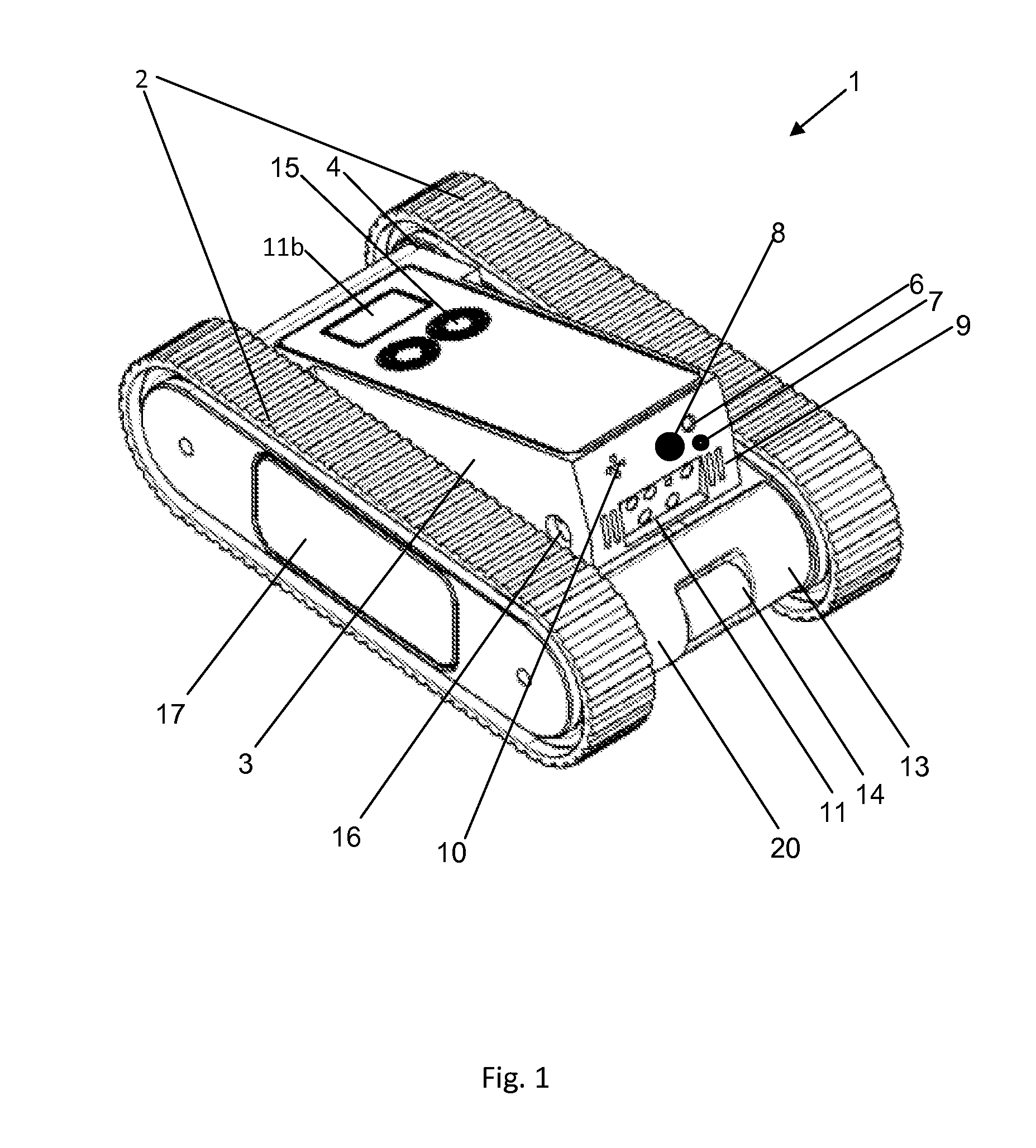
[0068]For a better understanding of the invention and to show how the same may be carried into effect, reference will now be made, purely by way of example, to the accompanying drawings. With specific reference to the drawings in detail, it is stressed that the particulars shown are by way of example and for purposes of illustrative discussion of preferred embodiments of the present invention only, and are presented for the purpose of providing what is believed to be the most useful and readily understood description of the principles and conceptual aspects of the invention. In this regard, no attempt is made to show structural details of the invention in more detail than is necessary for a fundamental understanding of the invention. From the description taken together with the drawings it will be apparent to those skilled in the art how the several forms of the invention may be embodied in practice.

[0069]FIG. 1 schematically shows a perspective view of the basic components of a pre...


PUM


Abstract

A robotic platform is presented, having a tiltable operational assembly. The operational assembly incorporates imaging means, designation means and operational means in a synchronized manner thus simplifying the maneuvering of the robotic platform and the operation of its operational means by a remote operator. The operational assembly can be tilted backwards in order to shift the center of gravity of the robotic platform towards its rear to decrease pressure from the front end of the robotic platform to the ground. Alternatively, the operational assembly can be used as an arm which applies pressure over obstacles to raise its distal end from the ground while overcoming obstacles. Tilting the operational assembly also provides double-sided operation of the robotic platform without the need to perform maneuvers which flip the entire robotic platform.

Description

[0001]This patent application claims the benefit of U.S. Provisional Patent Application No. 61 / 231,031 filed 4 Aug. 2009.FIELD AND BACKGROUND OF THE INVENTION[0002]The art of robotics has increasingly developed throughout the years, and many solutions have been offered for remotely controlling a robotic platform with extended operational and maneuvering capabilities.[0003]The solutions offered by the art are usually customized to the requirements for which a robotic platform is designed.[0004]One major challenge in the field of robotics is mobility, in other words, the ability to drive a robotic platform from one point to another. This allegedly simple challenge comprises a few challenging tasks, which can be generally categorized as follows: (i) incorporating a driving mechanism to provide propelling power to the robotic platform, (ii) incorporating sensors and communication means to intuitively control the driving mechanism and (iii) incorporating mechanisms to overcome obstacles....

Claims


Application Information

Patent Timeline
IPC IPC(8): B62D55/00
CPCB62D55/075
Inventor GAL, EHUD
Owner DEFENSE VISION
Learn More