Imaging apparatus

a technology of imaging apparatus and image, which is applied in the field of imaging apparatus, can solve the problems of increasing the number of memory accesses and memory capacity in use, the inability of the technique to fully satisfy each of the capturing objectives, and the inability to fully satisfy the capturing objective, so as to achieve the effect of simplifying the structure of the imaging apparatus, improving the level of visibility, and finding easy

Active Publication Date: 2011-02-10
PANASONIC SEMICON SOLUTIONS CO LTD
View PDF8 Cites 26 Cited by
  • Summary
  • Abstract
  • Description
  • Claims
  • Application Information

AI Technical Summary

Benefits of technology

[0018]The area specifying unit may (i) include a motion estimating unit which estimates an area in which a motion is estimated by motion estimation, and (ii) specify the area estimated by the motion estimating unit as the watch area. This structure makes possible automatically selecting and capturing a watch area showing a motion, which is useful in a surveillance camera.
[0019]The area specifying unit may (i) include an eye-gaze detecting unit which detects an eye gaze of a user to specify an area at which the user is watching using the detected eye gaze, and (ii) select the area specified by the eye-gaze detecting unit as the watch area. This structure can alleviate a troublesome manual selection operation of the user, and specify any given watch area. The imaging apparatus according the aspect of the present invention may further include a sub image information generating unit which records information indicating the watch area as additional information in the recording medium, the watch area being specified by the area specifying unit. This structure allows watch area information selected by the area specifying unit to be included in storage data as additional information which in not an image, the area specifying unit which is included in the sub image information generating unit.<0) As a result, the watch area can be easily found when data in the recording medium is reproduced.
[0020]The imaging apparatus according to the aspect in the present invention may include a displayin

Problems solved by technology

Thus, unfortunately, the technique cannot fully satisfy each of capturing objective.
These cutout and size conversion cause (i

Method used


Image

  • Imaging apparatus
  • Imaging apparatus
  • Imaging apparatus

Examples


embodiment 1

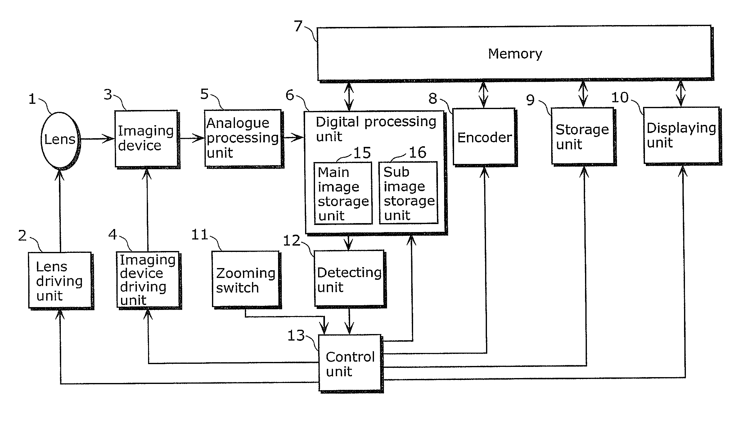
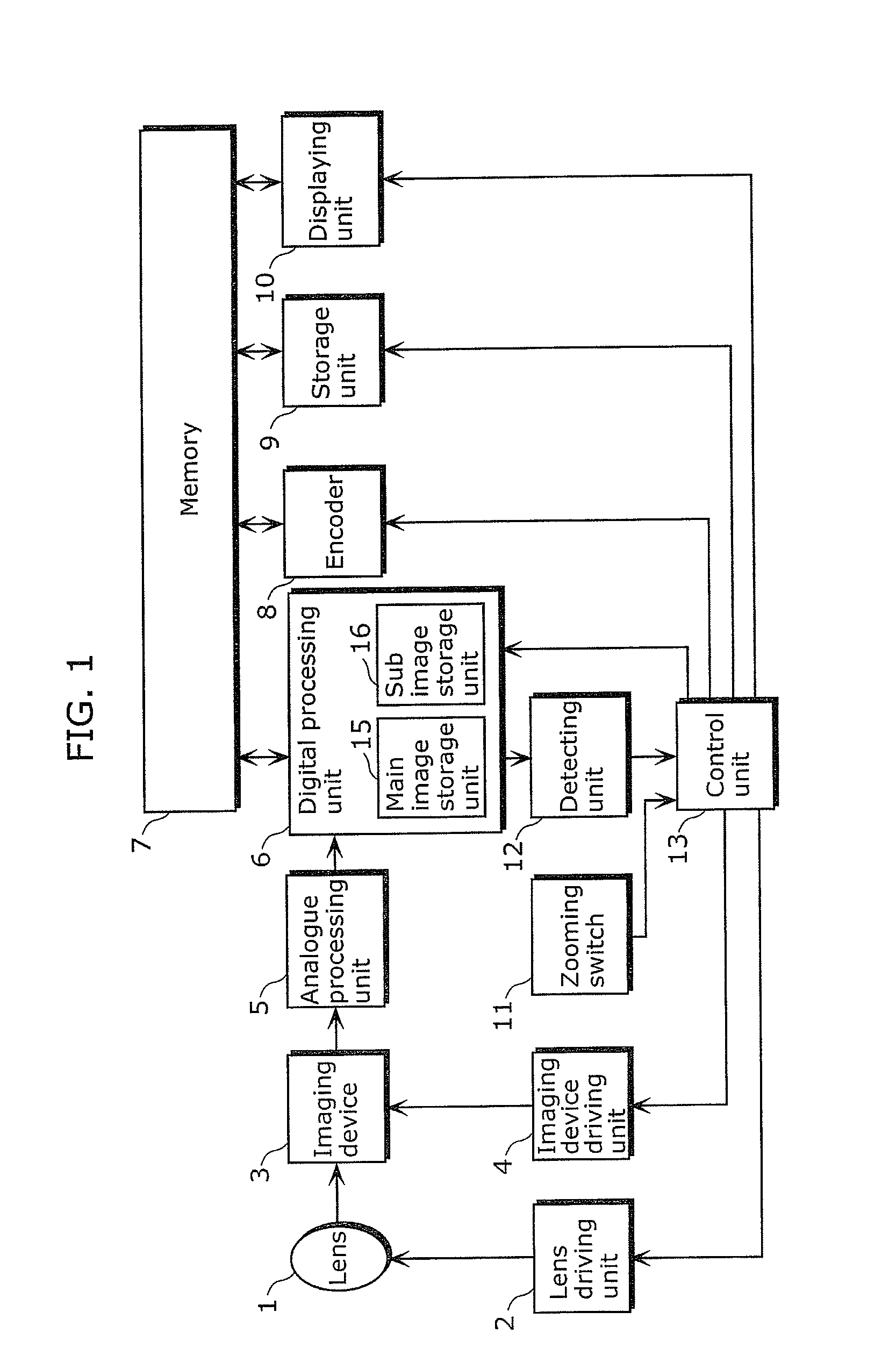
[0048]FIG. 1 is a block diagram showing a system structure of an imaging apparatus according to Embodiment 1. The imaging apparatus includes the following: a lens 1 which is an optical element and capable of zooming; a lens driving unit 2 which drives the lens 1 and causes the lens 1 to perform zooming; a zooming switch 11 which designates a zooming direction and a zooming amount of the lens 1; an imaging device 3 which photoelectrically-converts light of an object passing through the lens 1 to provide an image signal; an imaging device driving unit 4 which generates a driving signal to be used for taking any given area from the imaging device 3 as an image; an analogue processing unit 5 which performs various kinds of processing, such as noise reduction, gain control, and analogue-digital conversion, on the analogue image signal provided from the imaging device 3; a digital processing unit 6 which performs Y / C conversion and electronic zooming on the digitalized image signal; a mem...

embodiment 2

[0091]An imaging apparatus according to Embodiment 2 determines a watch area via an operation of a user. In Embodiment 2, constituent features identical to those in Embodiment 1 share the same numerical references. Thus, detailed description thereof shall be omitted.

[0092]FIG. 12 is a block diagram showing a system structure of the imaging apparatus according to Embodiment 2. The imaging apparatus includes the following: the lens 1 which is an optical element and capable of zooming; the lens driving unit 2 which drives the lens 1 and causes the lens 1 to perform zooming; the zooming switch 11 which designates a zooming direction and a zooming amount of the lens 1; the imaging device 3 which photoelectrically-converts light of an object passing through the lens 1 to provide an image signal; the imaging device driving unit 4 which generates a driving signal to be used for taking any given area from the imaging device 3 as an image; the analogue processing unit 5 which performs various...


PUM


Abstract

An imaging apparatus according to an implementation of the present invention is connected to a memory and includes: an imaging device reading any given area; a main image storage unit reading an image of a main image area, the image representing a whole image formed on the imaging device, and store in the memory an image associated with the read image as a main image; a sub image storage unit reading an image of a watch area from the imaging device, the watch area being an area to be watched, and store the read image in the memory as a sub image; an encoder encoding the main image and the sub image stored in the memory by the main image storage unit and the sub image storage unit; and a recording unit recording the main image and the sub image encoded by the encoder on a recording medium.

Description

CROSS REFERENCE TO RELATED APPLICATION[0001]This is a continuation application of PCT application No. PCT / JP2009 / 001918 filed Apr. 27, 2009, designating the United States of America.BACKGROUND OF THE INVENTION[0002](1) Field of the Invention[0003]The present invention relates to imaging apparatuses, and in particular, to an imaging apparatus which employs a high-speed imaging device and a high-definition imaging device to obtain images at once out of one input image.[0004](2) Description of the Related Art[0005]There are imaging apparatuses performing the following: employing a lens to form an image of an object on an imaging device; providing various kinds of signal processing to the image data obtained via photoelectric conversion; and displaying the image of the object on a liquid crystal monitor as well as recording the image in a recording medium. Such imaging apparatuses have been practically realized as digital still cameras and digital video cameras and have become widely av...

Claims


Application Information

Patent Timeline
IPC IPC(8): H04N5/76
CPCH04N5/232H04N5/23293H04N2101/00H04N9/8042H04N9/8227H04N5/23296H04N23/61H04N23/635H04N23/69
Inventor TAKAHASHI, ATSUSHI
Owner PANASONIC SEMICON SOLUTIONS CO LTD
Why Eureka
Try Eureka