
Scanning device and scanning method thereof

Inactive Publication Date: 2011-02-10
QISDA SUZHOU
View PDF5 Cites 6 Cited by
  • Summary
  • Abstract
  • Description
  • Claims
  • Application Information

AI Technical Summary

Benefits of technology

[0018]According to the scanning method of the invention, in the step D, an exposure time of the light source is increased or decreased.
[0019]To resolve the problems such as color aberration and brightness change, which occur to the portable scanner due to temperature change, the invention provides a scanning device with automatic calibration of brightness and colors, so that the user no more need to perform manual calibration after the occurrence of brightness change or color aberration. The invention provides the user with great convenience.

Problems solved by technology

Due to the restrictions in the design, the portable scanner or the paper-feed scanner normally does not provide the standard document that is fixed in the scanning device.
Unlike the flat-bed scanner, the portable scanner or the paper-feed scanner cannot perform at anytime.
However, a problem arises.
That is, after a scanner has worked for a period of time, or the environmental temperature of the scanner has changed, the brightness of the LED of the CIS will change due to the change in the environmental temperature, and such brightness change will make the brightness of the scanned image change or even result in color aberration.

Method used


Image

  • Scanning device and scanning method thereof
  • Scanning device and scanning method thereof
  • Scanning device and scanning method thereof

Examples

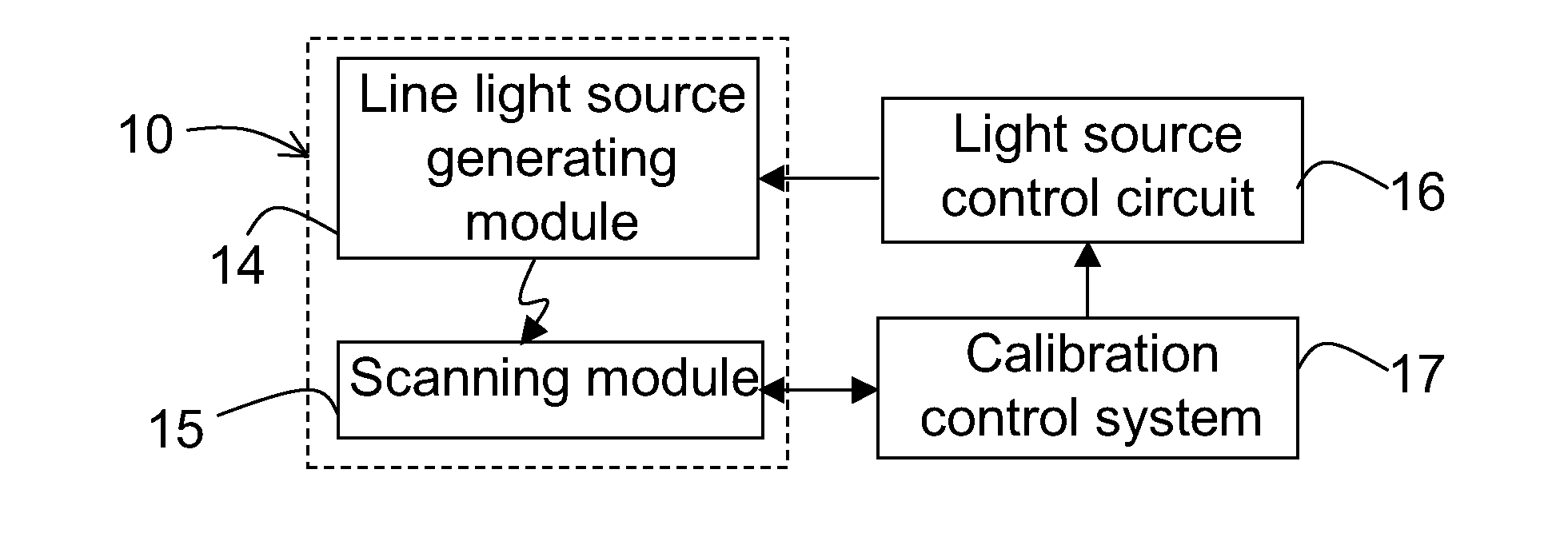
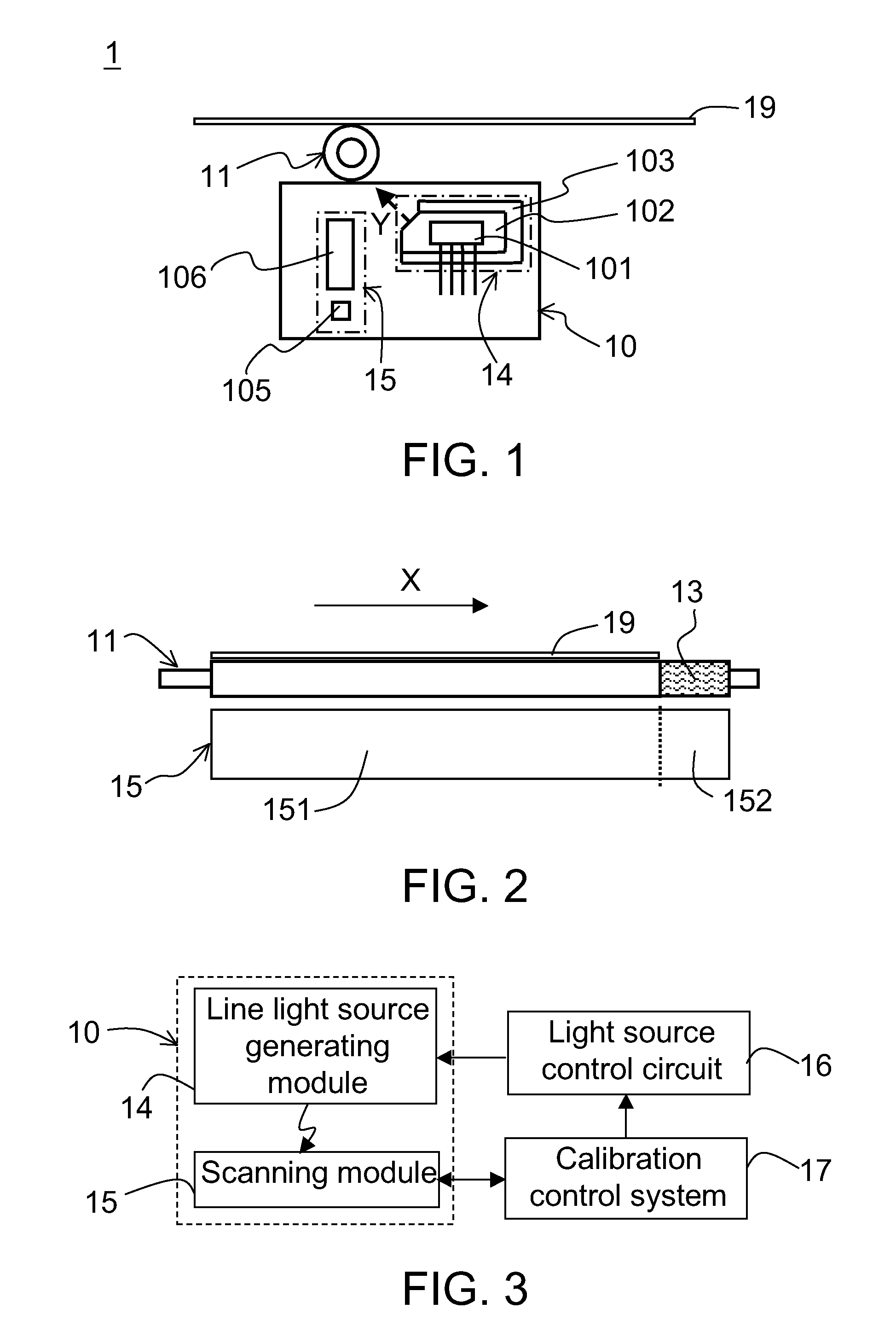
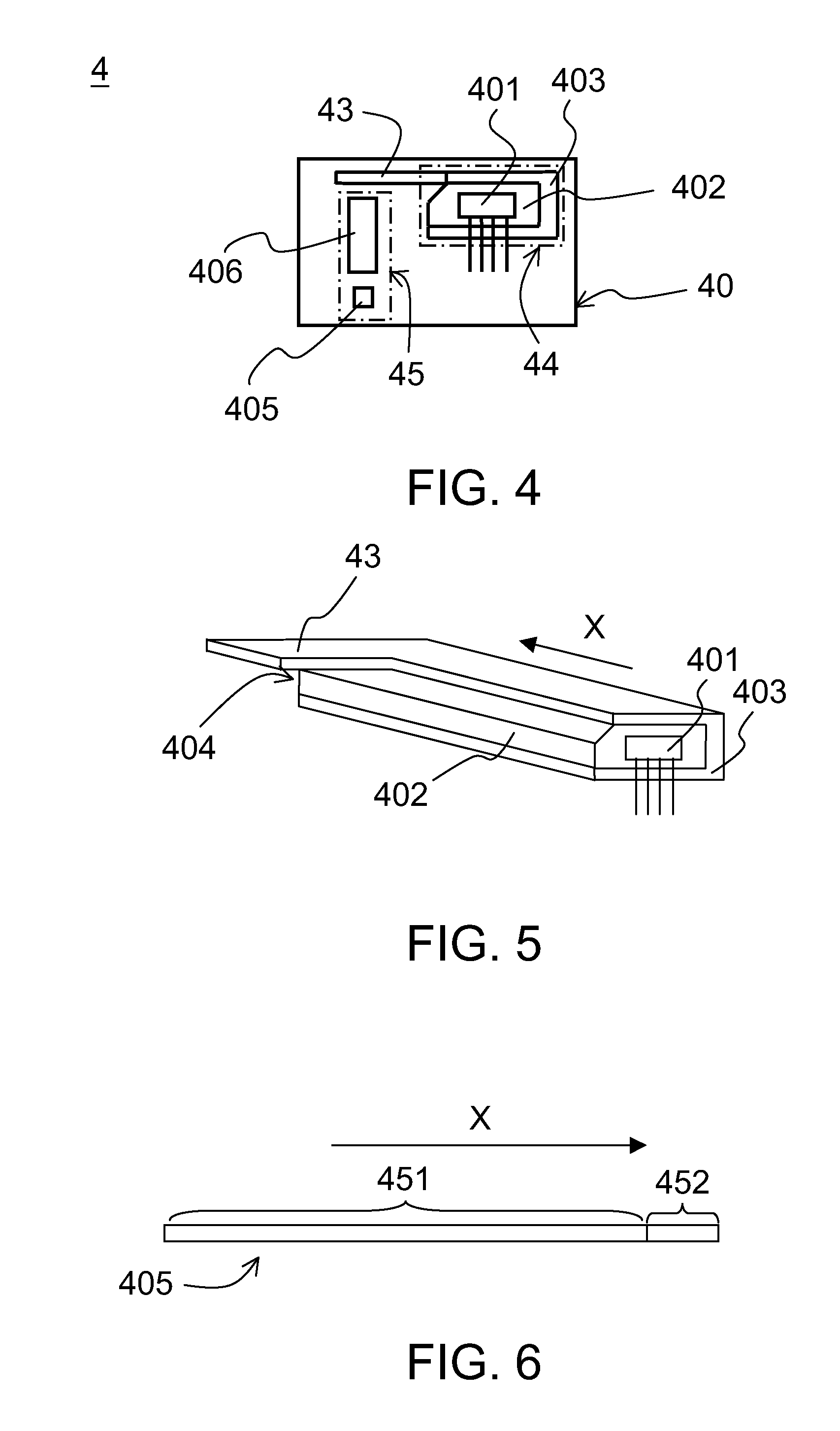

Embodiment Construction

[0030]Detailed descriptions of the objects, structures, features and functions of the invention are disclosed in a number of embodiments below.

[0031]Referring to FIG. 1 and FIG. 2. FIG. 1 shows a structural diagram of a scanning device 1 according to an embodiment of the invention. FIG. 2 shows a position diagram of a calibration portion 13 according to an embodiment of the invention. The scanning device 1 includes a scanning group 10, a paper-feed roller 11 and a calibration portion 13. The scanning group 10 includes a line light source generating module 14 and a scanning module 15. The line light source generating module 14 includes a point light source 101, a light-guiding plate 102 and a casing 103. The light emitted by the point light source 101 along a first direction X is converted into a line light source through the light-guiding plate 102. The light-guiding plate 102 is disposed in the casing 103. The light emitted by the line light source along a second direction Y is emi...


PUM


Abstract

A scanning device and a scanning method thereof are provided. The scanning device includes a scanning group, a paper-feed roller and a calibration portion. The scanning group includes a line light source generating module and a scanning module. The line light source generating module includes a point light source, a light-guiding plate and a casing. The light emitted by the point light source along a first direction is converted into a line light source through a light-guiding plate disposed in the casing. The light emitted by the line light source along a second direction is emitted from an opening of the casing. The scanning module, along the first direction, includes a scan document region and a calibration region. The light reflected through the to-be-scanned document is received in the scan document region. The calibration portion disposed on the casing or the paper-feed roller corresponds to the calibration region.

Description

[0001]This application claims the benefit of People's Republic of China application Serial No. 200910163864.4, filed Aug. 7, 2009, the subject matter of which is incorporated herein by reference.BACKGROUND OF THE INVENTION[0002]1. Field of the Invention[0003]The invention relates in general to a scanning device and a scanning method thereof, and more particularly to a scanning device with automatic calibration of brightness and colors and a scanning method thereof.[0004]2. Description of the Related Art[0005]The portable scanner normally adopts the contact image sensor (CIS) as an image collecting element, and the color CIS normally adopts the RGB (red / green / blue) light emitting diodes (LEDs) as a light source for illumination. Inside the portable scanner, electronic elements such as motor, driving circuit board and LED light source generate heat during operation. The temperature inside the scanning device changes accordingly with the change in the temperature of the working environ...

Claims


Application Information

Patent Timeline
IPC IPC(8): H04N1/00
CPCH04N1/00002H04N2201/03145H04N1/00023H04N1/00034H04N1/00045H04N1/0005H04N1/00055H04N1/00063H04N1/00087H04N1/02835H04N1/1215H04N1/125H04N1/193H04N2201/0081H04N2201/0096H04N2201/03112H04N2201/03125H04N2201/03141H04N1/00013
Inventor YI, YONG-XIANG
Owner QISDA SUZHOU
Learn More