Cover mechanism and electronic device using same

Inactive Publication Date: 2011-02-10
SHENZHEN FUTAIHONG PRECISION IND CO LTD +1
View PDF11 Cites 29 Cited by
  • Summary
  • Abstract
  • Description
  • Claims
  • Application Information

AI Technical Summary

Problems solved by technology

However, the covers are often not permanently attached to the electronic device.
Thus,

Method used


Image

  • Cover mechanism and electronic device using same
  • Cover mechanism and electronic device using same
  • Cover mechanism and electronic device using same

Examples


Embodiment Construction

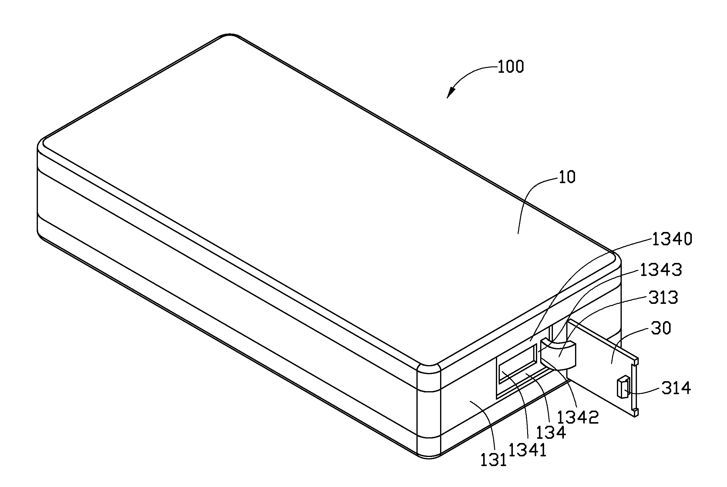
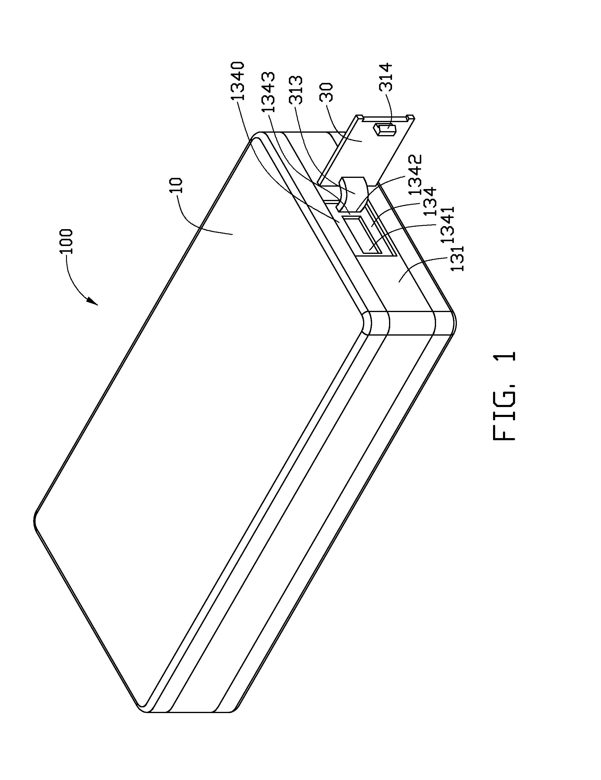
FIG. 1 shows an exemplary embodiment of a cover mechanism 30 used with an electronic device 100, such as a mobile phone.

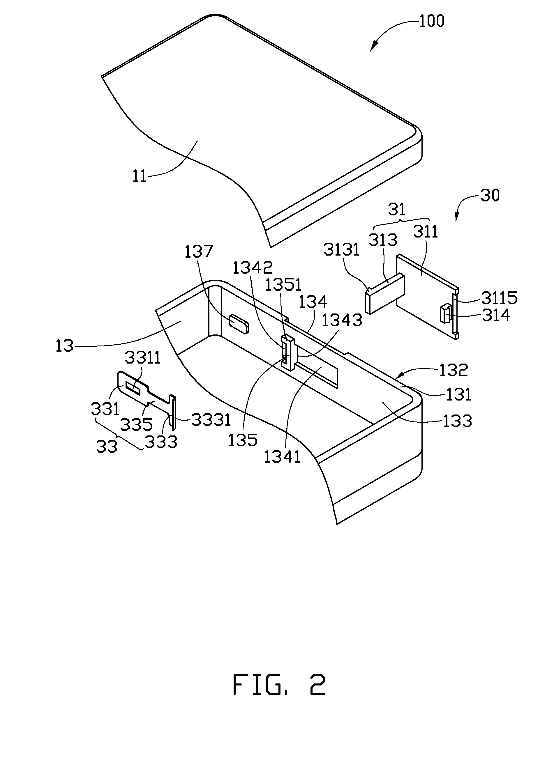
The mobile phone 100 includes a cover member 11, and a main body 13. The cover member 11 is detachably attached to one side of the main body 13. The main body 13 includes at least one wall 131 communicating with an inside of the mobile phone 100. The wall 131 includes an outer surface 132 and an inner surface 133. The outer surface 132 defines a rectangular recess 134 with a recess wall 1340. The recess wall 1340 defines an opening 1341 and a latching slot 1342. In this embodiment, the opening 1341 is a connector interface hole. The opening 1341 is spaced from the latching slot 1342 by a beam 1343. A protrusion 135 is formed on the beam 1343 of the inner surface 133. The protrusion 135 can be substantially [-shaped, and includes two extending ends 1351. The extending ends 1351 are positioned at two ends of the latching slot 1342 on inner surface 133. A block 137 is...


PUM


Abstract

A cover mechanism for an electronic device includes a protective cover and a resisting member. The protective cover includes a cover portion, and an arm portion. The arm portion allows the protective cover to rotate relative to the electronic device. The resisting member is attached to the electronic device, and prevents the arm portion from separating from the electronic device.

Description

BACKGROUND1. Technical FieldThe present disclosure relates to cover mechanisms used in electronic devices (e.g., mobile phones).2. Description of Related ArtElectronic devices usually have external interfaces (e.g., universal serial bus (USB)) for electrically connecting external devices (e.g., printers), accessories (e.g., USB flash drives) or other electronic devices. Such external interfaces are usually protected by cover mechanisms from e.g., dust or water, to maintain proper functioning.The cover mechanisms usually include covers with locks. The covers are typically locked to the electronic devices by latches to cover the area through which the interfaces of electronic devices are exposed. However, the covers are often not permanently attached to the electronic device. Thus, the covers may easily be misplaced or lost when not locked to the electronic devices.Therefore, there is room for improvement within the art.BRIEF DESCRIPTION OF THE DRAWINGSMany aspects of the embodiments ...

Claims


Application Information

Patent Timeline
IPC IPC(8): H05K5/00
CPCH04M1/0214H05K5/0239H04M1/0274Y10T292/0863H05K5/03
Inventor LONG, JIANGFU, PING-KUNXIONG, BIN
Owner SHENZHEN FUTAIHONG PRECISION IND CO LTD
Why Eureka
Try Eureka