Objective lens for endoscope, and endoscope

a technology of endoscope and objective lens, which is applied in the field of endoscope, can solve the problems of increasing the time for diagnosis, the inability to turn the tip portion to a desired direction, and the burden on both the operator and the patient, and achieves the effects of wide angle of view, convenient optical performance, and compact siz

Active Publication Date: 2013-03-07
HOYA CORP
View PDF3 Cites 18 Cited by
  • Summary
  • Abstract
  • Description
  • Claims
  • Application Information

AI Technical Summary

Benefits of technology

[0010]When SF gets larger than the upper limit of the condition (2), feeling of insertion which can be provided when the electronic scope is inserted into a tube cavity is lost. Furthermore, regarding the negative front group lens, the radius of curvature of the object side surface becomes small and thereby the projecting amount of the object side surface increases. Therefore, the detergent property decreases and the object side surface becomes easy to be damaged. When SF gets smaller than the lower limit of the condition (2), the resolution in the peripheral apportion of the observation field in which a subject such as a tube wall is displayed decreases, which is not suitable for observation of a tube cavity. Furthermore, regarding the negative front group lens, the radius of curvature of the object side surface is large, and therefore the incident angle to the object side surface becomes larger and the loss of light amount becomes easy to occur.
[0027]According to the invention, an objective lens for an endoscope and an endoscope designed to be compact in size and to have a wide angle of view while maintaining suitable optical performance are provided.

Problems solved by technology

However, if the diameter of a tube cavity is small, the motion of the tip portion is restricted, and thereby it might become impossible to turn the tip portion to a desired direction.
Furthermore, in the case where the diagnosis is performed while variously changing the direction of the tip portion, if the operation is complicated, the time for diagnosis increased.
This is a burden for both of an operator and a patient and is not desirable.
However, if a designer tries to widen the angle of view by employing a high refractive index lens, the chromatic aberration of magnification might occur largely and the image quality might be deteriorated.
In particular, there is a problem that the color shift occurs significantly at a part closer to the periphery of the observation field, and the optical performance suitable for observation for a tube cavity cannot be achieved.

Method used


Image

  • Objective lens for endoscope, and endoscope
  • Objective lens for endoscope, and endoscope
  • Objective lens for endoscope, and endoscope

Examples


example 1

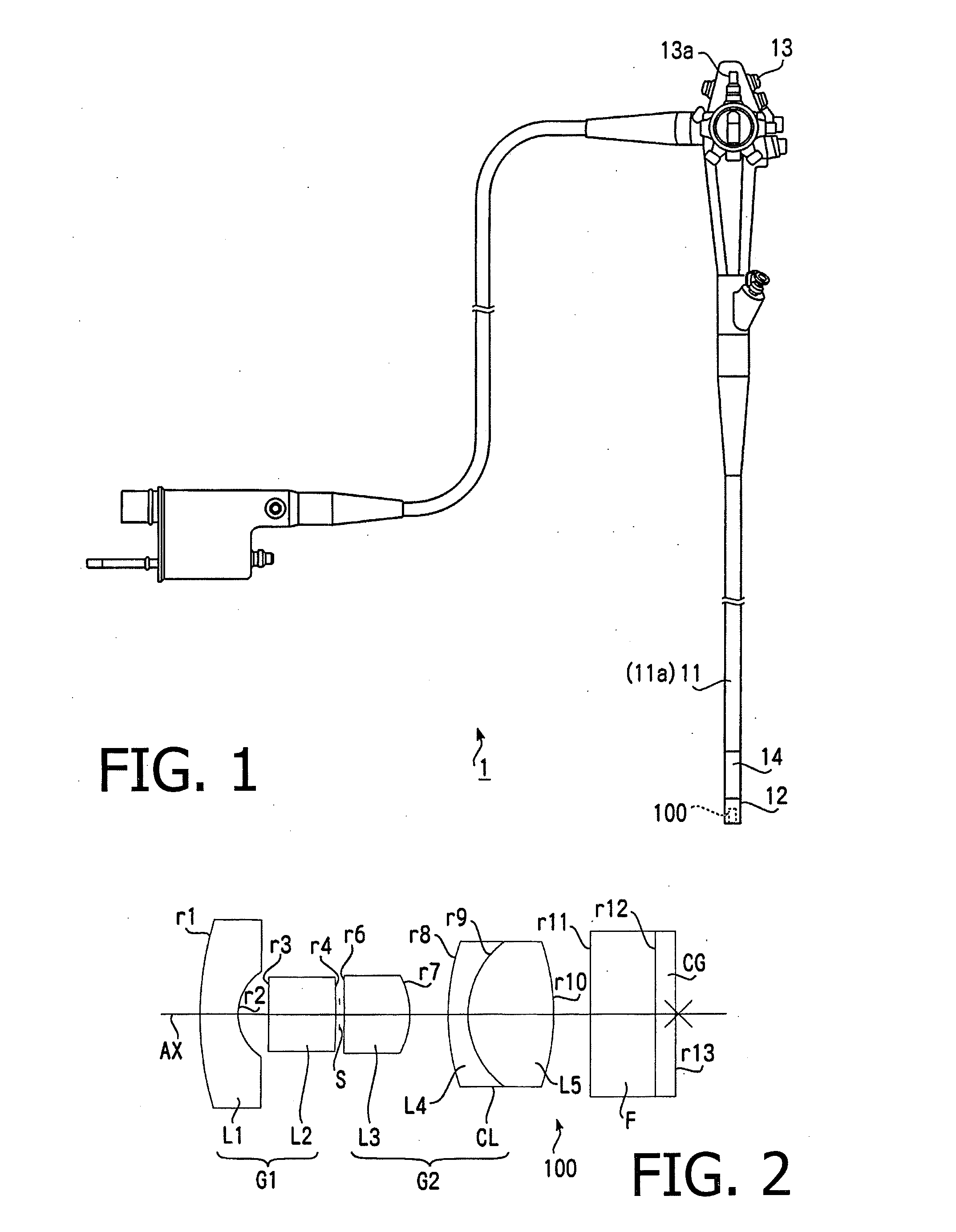
[0082]As described above, the objective lens 100 for an endoscope according the example 1 of the invention is shown in FIG. 2. Table 1 shows a concrete numeric configuration (design values) of the objective lens 100 for an endoscope (and optical components arranged on the rear side thereof) according to the example 1. In Table 1, the surface number n corresponds to the surface reference rn in FIG. 2, excepting the surface number 5 for the aperture stop S. In Table 1, R (unit: mm) denotes the radius of curvature of each surface an optical component, D (unit: mm) denotes a thickness of an optical component or an interval between optical components, N(d) denotes an refractive index at d-line (wavelength of 588 nm), and νd denotes Abbe number at d-line. Table 2 shows specifications (F number, the focal length (unit: mm) of the entire system, the optical magnification, half view angle (unit: deg), and the image height (unit: mm)) of the objective lens 100 for an endoscope.

TABLE 1No.RDN(d...

example 2

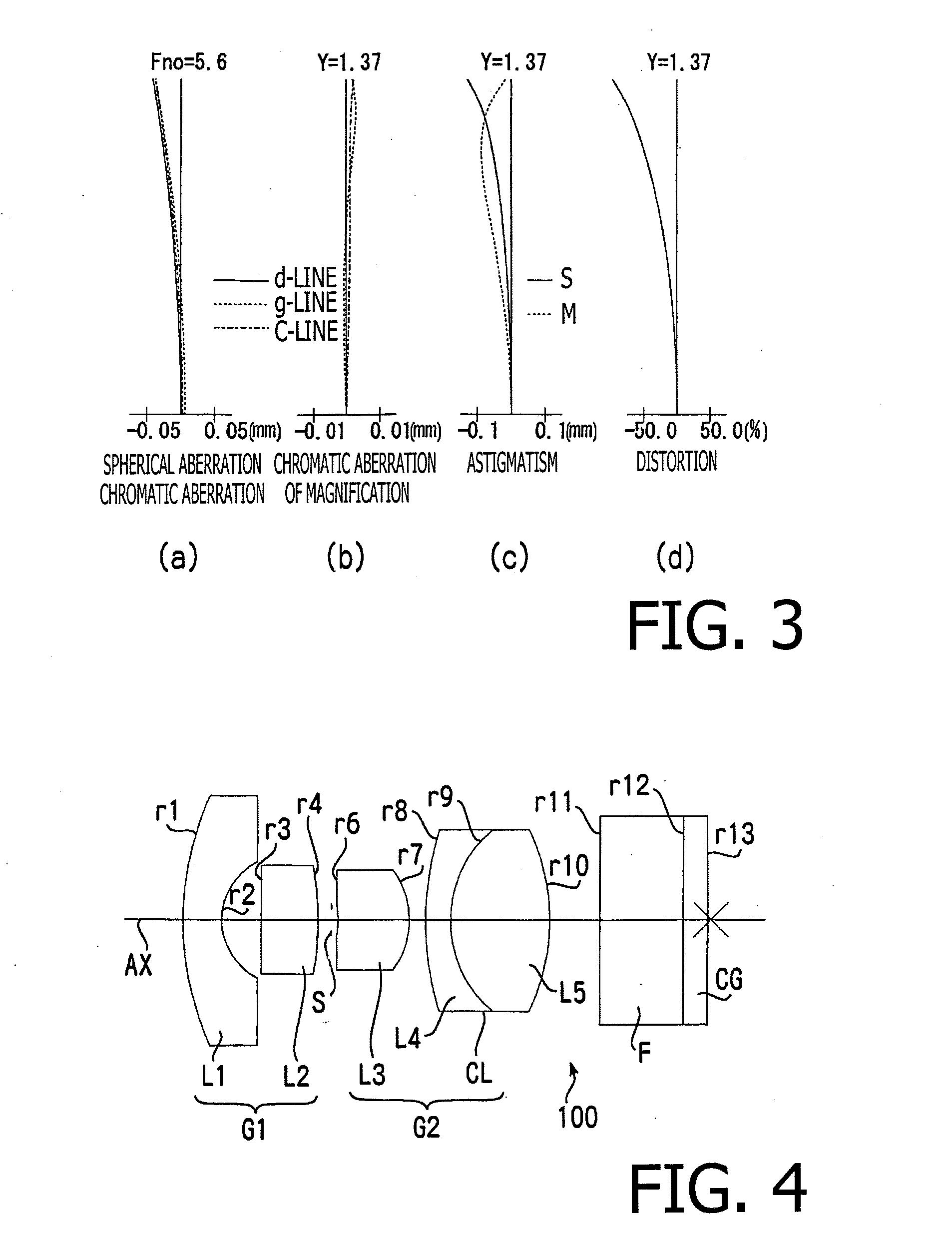
[0084]FIG. 4 is a cross sectional view illustrating the arrangement of the optical components including the objective lens 100 for an endoscope according to the example 2. As shown in FIG. 4, the objective lens 100 for an endoscope according to the example 2 has the same number of lenses as that of the objective lens 100 for an endoscope according to the example 1. FIGS. 5(a) to 5(d) are aberration diagrams (the spherical aberration, the longitudinal chromatic aberration, the chromatic aberration of magnification, the astigmatism, and the distortion) of the objective lens 100 for an endoscope according to the example 2. Table 3 shows an concrete numeric configuration of the optical components including the objective lens 100 for an endoscope according to the example 2, and Table 4 shows specifications of the objective lens 100 for an endoscope according to the example 2. As shown in Tables 3 and 4 and FIGS. 5(a) to 5(d), the objective lens 100 for an endoscope according to the examp...

example 3

[0085]FIG. 6 is a cross sectional view illustrating the arrangement of the optical components including the objective lens 100 for an endoscope according to the example 3. As shown in Table 3 indicated below, the objective lens 100 for an endoscope according to the example 3 has a half view angle exceeding 95°. Therefore, it is difficult to suitably correct the curvature of field if the lens arrangement is the same as that of the example 1 or 2. For this reason, as shown in FIG. 6, a positive lens L6 is arranged between the positive lens L3 and the cemented lens CL so as to suitably correct the curvature of field. That is, in the example 3, the second lens group G2 has three lenses including the positive lens L3, the positive lens L6 and the cemented lens CL. The first lens group G1 has the same number of lenses as that of the first lens group G1 of the example 1. FIGS. 7(a) to 7(d) are aberration diagrams (the spherical aberration, the longitudinal chromatic aberration, the chromat...


PUM


Abstract

An objective lens for an endoscope, comprising a first lens group having a negative power, an aperture stop, and a second lens group having a positive power arranged in this order from an object side, wherein the first lens group comprises at least a negative front group lens having a concave surface facing an image side, and a positive front group lens having a convex surface facing the image side arranged in this order from the object side, and the second lens group comprises at least a positive rear group lens having a convex surface facing the image side and a cemented lens formed by cementing together a negative lens and a positive lens being arranged in this order from the object side, and wherein the objective lens for an endoscope is configured to satisfy a predetermined condition.

Description

TECHNICAL FIELD[0001]The present invention relates to an endoscope for observing an inside of a living body, and an objective lens for an endoscope installed in a tip portion of the endoscope. Specifically, the present invention relates to an endoscope and an objective lens for an endoscope designed to have a wide angle of view and to be compact in size while maintaining suitable optical performance.BACKGROUND OF THE INVENTION[0002]As an apparatus for examining a body cavity of a patient, an endoscope is generally known and has been put into practical use. The endoscope of this type is required to be compact in size so that a tip portion thereof can be smoothly inserted into a minute gap. The design minimum outer diameter of the tip portion is substantially defined by a large size component installed therein. One of such large size components is an objective lens for endoscope. To select a small objective lens for an endoscope as a component to be installed is an effective measure f...

Claims


Application Information

Patent Timeline
Patent Type & Authority Applications(United States)
IPC IPC(8): H04N5/232
CPCG02B23/243G02B13/16
Inventor FUJII, SACHIKO
Owner HOYA CORP
Why Eureka
Try Eureka