Method and Apparatus for Distortion of Audio Signals and Emulation of Vacuum Tube Amplifiers

a vacuum tube amplifier and audio signal technology, applied in the field of audio signal processing, audio recording software, guitar amplification systems, etc., can solve the problems of inefficient computational methods for achieving the computational tasks required to produce convincing results, loss of true non-linear dynamical behavior of tube amplifier stages, and inability to fully capture the characteristics of distortions

Inactive Publication Date: 2011-02-10
GALLO MARC NICHOLAS
View PDF34 Cites 10 Cited by
  • Summary
  • Abstract
  • Description
  • Claims
  • Application Information

AI Technical Summary

Benefits of technology

[0022]It is still a further object of this invention to provide a means of an efficient implicit step-method numerical integra

Problems solved by technology

Prior attempts to emulate the effects of vacuum tubes with software-based or digital tube-modeling algorithms have either failed to fully capture the characteristics of these distortions and faithfully reproduce the dynamic and “warm” sound associated with tube amplifiers, or suffer from inefficient means of performing the computational tasks required to produce them convincingly.
By use of a chain of linear filters and distortion blocks, the true non-linear dynamical behavior of tube amplifier stages is lost.
Many non-linear transfer functions are described by fixed equations and lack means of adjustment of their shape, linear regions, and clipping characteristics.
Furthermore, little progress has been made to simplify the non-linear functions used to distort digital signals in these algorithms to improve their computational efficiency and permit greater numbers of them to run on signal processors.
Clipping is achieved with a basic hard-clipping algorithm and does not address controlling the curvature of the clipping regions parametric

Method used


Image

  • Method and Apparatus for Distortion of Audio Signals and Emulation of Vacuum Tube Amplifiers
  • Method and Apparatus for Distortion of Audio Signals and Emulation of Vacuum Tube Amplifiers
  • Method and Apparatus for Distortion of Audio Signals and Emulation of Vacuum Tube Amplifiers

Examples


Embodiment Construction

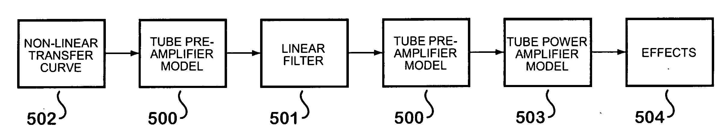
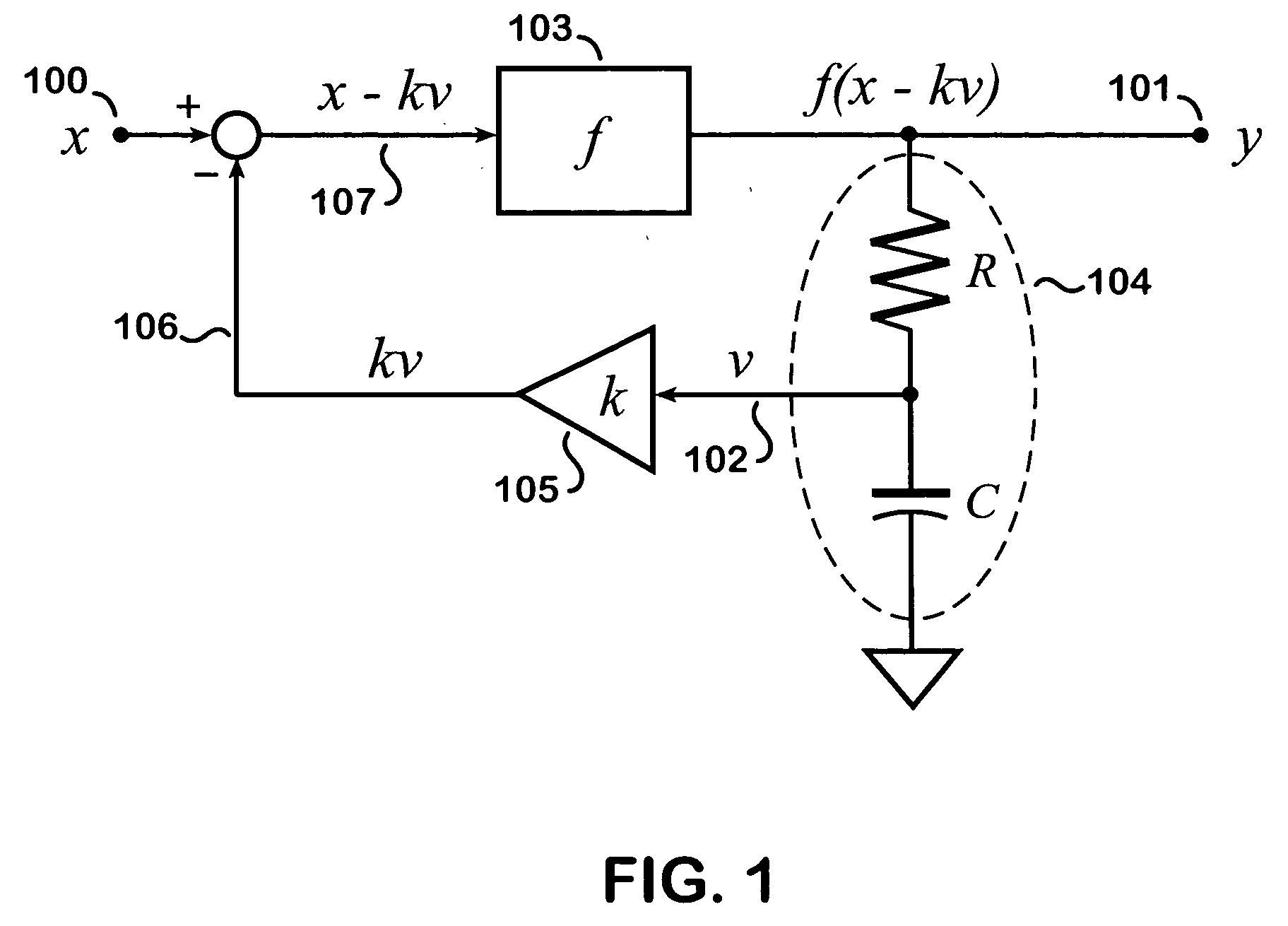
[0031]Referring to FIG. 1, a signal flow block diagram of a non-linear filter representing a simplified model of a vacuum tube, featuring an input, x 100, an output, y 101, and a capacitor voltage, v 102, is shown. This non-linear filter comprises a non-linear transfer function 103, an R-C network 104, and a feedback control 105. The output signal 101 is produced by applying the non-linear transfer function 103 to the difference 107 of the input signal 100 and feedback signal 106. The feedback signal is generated by the R-C network 104, which derives its input from the output signal 101. The gain of the feedback signal is adjusted by the feedback control 105 which scales the capacitor voltage, v 102, with by the negative feedback parameter, k. This arrangement is designed to add dynamic characteristics and spectral control to the model, mimicking the same effect found in real tube amplifier stages.

[0032]The choice of values for the R-C network and feedback control parameters affect ...


PUM


Abstract

A method for digitally processing audio signals to emulate the effects of vacuum tube amplifiers and preamplifiers, musical instrument amplification systems, and distortion effects. By use of an implicit numerical method to estimate the response of a parametrically-controlled non-linear transfer function, non-linear filters, and feedback elements, the dynamic behavior and distortion effects of tube amplification stages are simulated. This provides the capability to reproduce the desired sounds of vintage and modern tube amplifier systems and effects with the conveniences and control associated with digital signal processing systems and software.

Description

CROSS-REFERENCE TO RELATED APPLICATIONS[0001]The following U.S. Patent documents relate to the present invention and are provided for reference.3,835,409September 1973Laub4,405,832September 1983Sondermeyer4,495,640January 1985Frey4,672,671June 1987Kennedy4,710,727December 1987Rutt4,811,401March 1989Brown Sr. et al.4,852,444August 1989Hoover et al.4,868,869September 1989Kramer4,949,177August 1990Bannister et al.4,991,218February 1991Kramer4,995,084February 1991Pritchard5,032,796July 1991Tiers et al.5,131,044July 1992Brown Sr. et al.5,248,844September 1993Kunimoto5,321,325June 1994Lannes5,524,055June 1996Sondermeyer5,528,532June 1996Shibutani5,570,424October 1996Araya et al.5,578,948November 1996Toyama5,596,646January 1997Waller Jr. et al.5,619,578April 1997Sondermeyer et al.5,647,004July 1997Sondermeyer et al.5,748,747May 1998Massie5,789,689January 1997Doidic et al.5,802,182September 1998Pritchard6,350,943February 2002Suruga et al.6,504,935January 2003Jackson6,611,854August 2003Amels...

Claims


Application Information

Patent Timeline
IPC IPC(8): H03G3/00
CPCG10H1/0091G10H3/187G10H2210/231G10H2210/315G10H2210/251G10H2210/281G10H2210/311G10H2210/235
Inventor GALLO, MARC NICHOLAS
Owner GALLO MARC NICHOLAS
Why Eureka
Try Eureka