
Underground positioning method based on directive antennae

A directional antenna and positioning method technology, applied in positioning, wireless communication, radio wave measurement system and other directions, can solve the problems of large transmission loss of leaky cables, signal fingerprint changes, affecting positioning accuracy, etc., to improve radiation utilization and position discrimination. Precise, long-distance effects

Inactive Publication Date: 2014-04-02
GCI SCI & TECH
View PDF4 Cites 8 Cited by
  • Summary
  • Abstract
  • Description
  • Claims
  • Application Information

AI Technical Summary

Problems solved by technology

[0004] The method of laying leaky cables in the tunnel has the following disadvantages: the transmission loss of leaky cables is large, and it is only suitable for scenarios with high and uniform coverage requirements; since the whole is a series system, in the case of a relatively long tunnel, the amplifiers need to be used in series. The system noise is relatively high, which reduces the reliability of the signal; if the length of the leaking cable is long, the signal attenuation will be obvious, and the cost of use will increase significantly
Positioning through location fingerprint technology has the following disadvantages: After the wireless base station is set up, it is necessary to record the location fingerprints (signal strength, etc.) of each space in the scene, which consumes a lot of manpower; Fingerprints are susceptible to interference, which affects positioning accuracy; when a wireless base station fails, the signal fingerprints in the nearby space will change, making positioning impossible

Method used


Image

  • Underground positioning method based on directive antennae

Examples


Embodiment Construction

[0014] In order to further illustrate the technical means adopted by the present invention and the achieved effects, the technical solutions of the present invention will be clearly and completely described below in conjunction with the accompanying drawings and preferred embodiments.

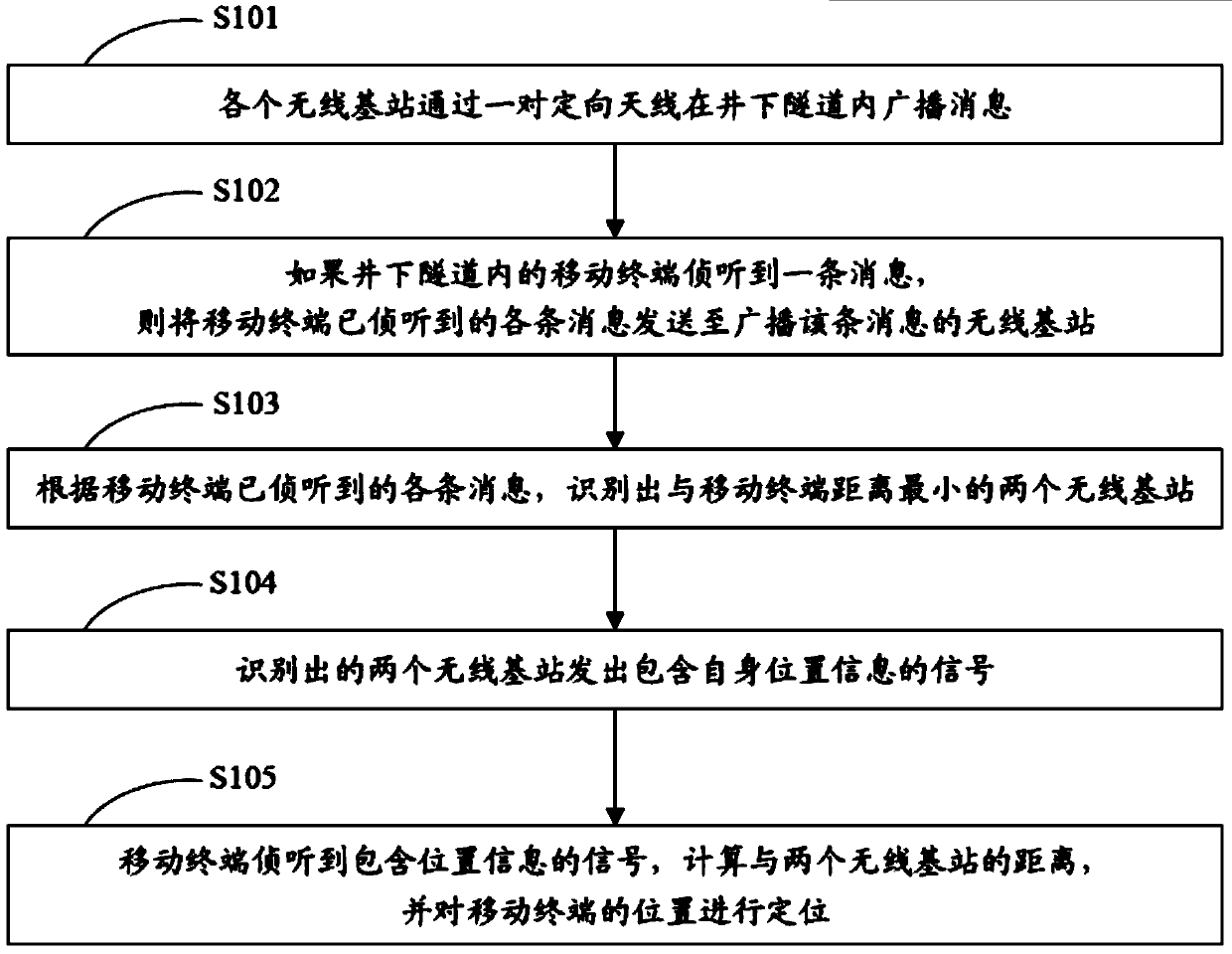
[0015] see figure 1 , is a schematic flowchart of the directional antenna-based downhole positioning method of the present invention.

[0016] A method for downhole positioning based on a directional antenna, comprising the following steps:

[0017] S101 Each wireless base station broadcasts messages in the underground tunnel through a pair of directional antennas;

[0018] S102 If the mobile terminal in the underground tunnel detects a message, then send each message detected by the mobile terminal to the wireless base station that broadcasts the message;

[0019] S103 Identify two wireless base stations with the smallest distance to the mobile terminal according to each message that the mob...


PUM


Abstract

The invention discloses an underground positioning method based on directive antennae. The method comprises the steps of broadcasting messages in an underground tunnel by each wireless base station through a pair of directive antennae; if a mobile terminal intercepts a message, sending each intercepted message to the wireless base station broadcasting the message; identifying two wireless base stations which are closest to the mobile terminal; sending signals comprising own position information by the two identified wireless base stations; intercepting the signals comprising the position information by the mobile terminal, computing the distances between the mobile terminal and the two wireless base stations, and positioning the position of the mobile terminal. The method has the advantage of low cost; the signal gain of the wireless base stations adopting the directive antennae is larger, the transmission distance is longer, and the number of the wireless base stations needing to be built is reduced; in addition, the judgment of the position is more accurate. When the accurate positioning of underground personnel is performed, the method is more economic, simpler and more reliable, and is applicable to the fields of underground positioning, tunnel positioning, indoor positioning and the like.

Description

technical field [0001] The invention relates to the technical field of underground positioning, in particular to an underground positioning method based on a directional antenna. Background technique [0002] With the development of the national economy and urban construction, the space for urban ground activities is becoming increasingly narrow, and urban infrastructure construction is gradually developing into underground space, for example: urban water supply and power supply systems are laid underground, underground railways and underground buses are increasingly popular, etc. . The in-depth utilization of underground space immediately brings a series of problems, among which the communication and positioning of underground tunnel staff is the key. Tunnels are constructed within the range of 5-20m underground, and the depth and cross-section of the same tunnel are different according to different construction methods and pipeline resources. Therefore, under normal cond...

Claims


Application Information

Patent Timeline
Patent Type & Authority Applications(China)
IPC IPC(8): H04W64/00G01S5/02
Inventor 余礼明林凡黄建青
Owner GCI SCI & TECH
Learn More