Fast low drop out (LDO) PFET regulator circuit

a pfet regulator and low dropout technology, applied in the field of pfet regulator circuits, can solve the problems of inability to control a fast pfet regulator, inability to adjust the pfet, so as to achieve the effect of increasing the signal gain

Active Publication Date: 2006-08-22
SKYWORKS SOLUTIONS INC
View PDF6 Cites 8 Cited by
  • Summary
  • Abstract
  • Description
  • Claims
  • Application Information

AI Technical Summary

Benefits of technology

[0006]In accordance with the invention there is provided a method of providing a regulated output voltage from a supply voltage source comprising: providing a field effect transistor (FET) regulator circuit comprising a regulating FET; operating the regulating FET in a saturation mode of operation; and, upon operation of the regulating FET in a triode region, providing increased signal gain to the regulating FET.

Problems solved by technology

However, this traditional system has transient response limitations, which affects an attack ramp and a decay ramp of the transmitted RF signal and also offers complications in calibration procedures.
Trauth et al. describe the difficulty of controlling a fast PFET regulator as it operates in the triode region.
The problem with not allowing operation of the PFET in the triode region, as described by Trauth et al., is that the PFET size has to be significantly increased in order to obtain the same DC low drop out voltage condition.
Otherwise the available supply voltage provided by the PFET regulator to the PA is restricted.
This restriction results in decreased power consumption efficiency of the combined PFET and PA circuit and is thus unacceptable.

Method used


Image

  • Fast low drop out (LDO) PFET regulator circuit
  • Fast low drop out (LDO) PFET regulator circuit
  • Fast low drop out (LDO) PFET regulator circuit

Examples


Embodiment Construction

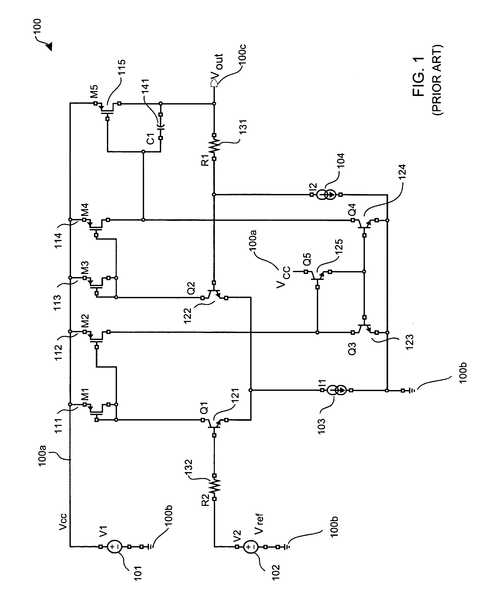
[0014]FIG. 1 illustrates a prior art LDO regulator circuit 100. A positive channel Field effect transistor (PFET) M5115 is a voltage regulating element. Transistors, Q1121, Q2122, Q3123, Q4124 and Q5125 form an operational amplifier circuit. A supply voltage is provided by a voltage source 101 disposed between a first supply voltage input port 100a and a second supply voltage input port 100b. A voltage reference source (Vref) 102 is connected through resistor R2132 to a base terminal of transistor Q1121. Because transistor Q2122 mirrors transistor Q1121, the potential on the base terminal of transistor Q2122 is approximately Vref. A first current source 103, for providing a first current (I1), is disposed between the emitter terminals of transistors Q1121 and Q2122 and the emitter terminals of transistors Q3123 and Q4124. The transconductance (gm) of the operational amplifier circuit is dependent upon the transistor pair Q1121 and Q2122 and is determined by the first current (I1). O...


PUM


Abstract

A low dropout (LDO) PFET regulator circuit is disclosed for operating in two modes of operation. For higher supply voltage potentials the LDO PFET regulator circuit operates normally, as supply voltage potential drops, the LDO PFET regulator operates in a second mode of operation where a decision circuit determines whether to supply a first boost current thereto in order to compensate for the reduced transimpedance of the first PFET.

Description

FIELD OF THE INVENTION[0001]The invention relates to the field PFET regulator circuits and more specifically to the field of low dropout (LDO) PFET regulator circuits.BACKGROUND OF THE INVENTION[0002]In typical RF systems, ON and OFF switching of transmitted RF signal power is controlled in order to avoid spectral splatter of the transmitted RF signal into adjacent transmission channels. Typically, a process known as burst shaping is employed in order to control the switching transients. In traditional RF transmission systems, a detector circuit in conjunction with a feedback loop is used to control PA output power. However, this traditional system has transient response limitations, which affects an attack ramp and a decay ramp of the transmitted RF signal and also offers complications in calibration procedures.[0003]A publication, entitled “An advanced controller for multi-band open loop power control mode RF power amplifier,” Microwave Engineering, July 2002, issued to Trauth et ...

Claims


Application Information

Patent Timeline
Patent Type & Authority Patents(United States)
IPC IPC(8): H03B21/00G05F1/56G05F1/575G05F3/16
CPCG05F1/575
Inventor WHITTAKER, EDWARD J. W.
Owner SKYWORKS SOLUTIONS INC
Why Eureka
Try Eureka