Supercharge Your Innovation With Domain-Expert AI Agents!

Transducer saddle for stringed instrument

a technology of transducer saddle and stringed instrument, which is applied in the field of stringed musical instruments, can solve the problems of micro-phonic noise, ineffectiveness of microphone, and inability to pick up vibrating sound, etc., and achieves the effects of eliminating micro-phonic noise, high efficiency, and high fidelity

Active Publication Date: 2011-02-24
BARBERA RICHARD
View PDF16 Cites 3 Cited by
  • Summary
  • Abstract
  • Description
  • Claims
  • Application Information

AI Technical Summary

Benefits of technology

[0010]There is provided a highly efficient means of coupling to sensors, vibrations from plucked musical instruments strings. In one aspect, the present invention is a transducer saddle system that mechanically conveys vertical aspects of string vibrations to transducers by way of cavities within a saddle body beneath a string saddle crown that establish vertically compliant areas within the saddle. The vertically compliant areas beneath each string are mechanically responsive to vertical string motion. Alternately, in some unitary saddle designs, the compliant areas within the saddle are additionally sensitive to horizontal string vibrations. These areas couple the strings to transducers mounted within said cavities, and are selectively sensitive to vertical string vibrations from the top of the saddle, beneath the string. This sensitivity does not respond to vibratory information from beneath the saddle and is sensitive from its top or positive Z axis direction primarily. This eliminates the introduction of micro-phonic noise from the body of the instrument in the amplified signal. Isolating the vertical component of the string vibration further maximizes fidelity, clarity of sound and responsiveness.

Problems solved by technology

The problem with using microphones is that the microphone picks up not only the sound of the vibrating string, but every other sound caused by playing the instrument, such as string noise, bumps and taps, as well as ambient noise from other instruments etc.
The microphone can further cause feedback by picking up noise from the instruments' vibrating top, which is further amplified by the surrounding speakers / amplifiers.
Also a microphone has a very limited volume range and is ineffective when competing with other amplified instruments.
Micro-phonic noise occurs when a pickup systems axis of sensitivity is mechanically coupled to the instruments resonant top.
Micro-phonic sensitivity also increases feedback sensitivity because certain resonant frequency sensitivities in the instrument top become magnified, causing an uncontrollable feedback loop when the amplified signal excites the instruments top and strings through sympathetic resonances.

Method used


Image

  • Transducer saddle for stringed instrument
  • Transducer saddle for stringed instrument
  • Transducer saddle for stringed instrument

Examples


first embodiment

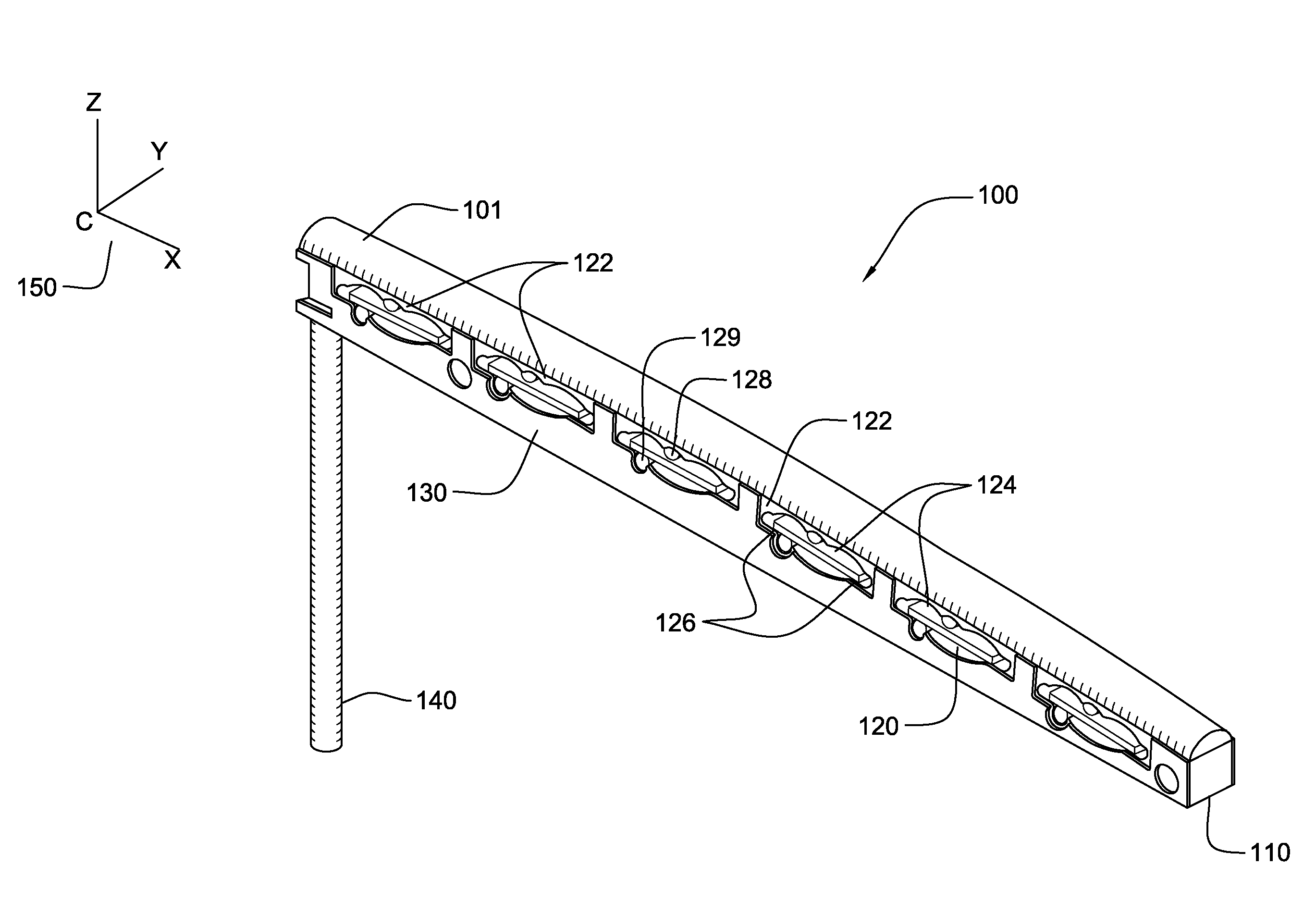
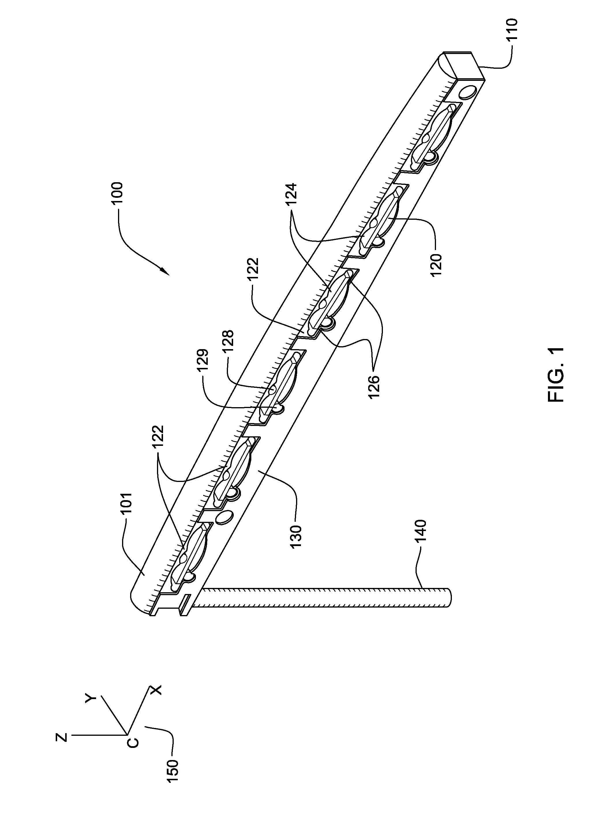
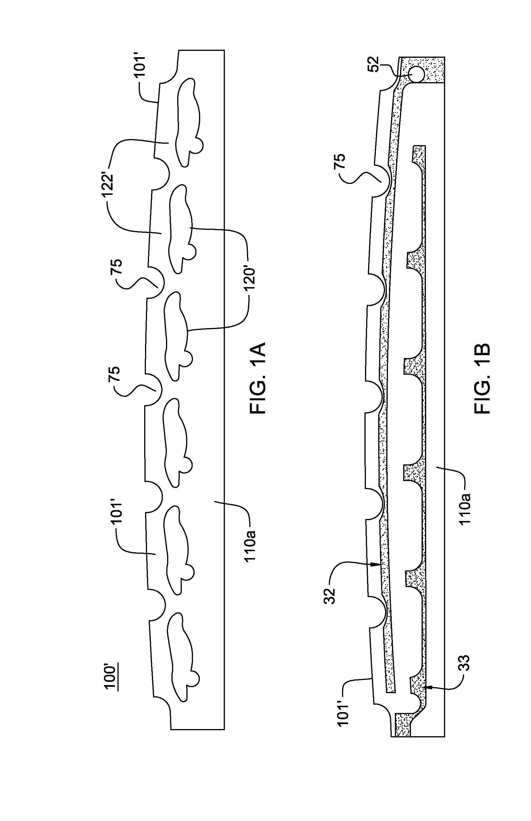
[0043]FIG. 1 shows a unitary string saddle system 100 according to an exemplary embodiment of the present invention. Top saddle strip 101 supports the tensioned strings (not shown) over the body portion 110. Body portion 110 comprises a laminated construction of printed circuit board or like materials, e.g., copper clad FR4, or may comprise similar structures for embedding a circuit path of conductor material such as copper. Within the body portion there is further included a plurality of embedded cavity structures 120 located in articulation with a respective string. In the embodiment depicted, there are 6 cavity structures 120; one for each string on a six-string musical instrument such as a guitar. The body portion 110 also comprises two opposing surfaces described in further detail in the following figures. Cavity structures 120 define and form a vertically compliant area of sensitivity 122 in the body portion that is responsive to vibratory energy from the corresponding string....

second embodiment

[0105]In an alternative embodiment, the entire string saddle and body is divided into mechanically and electrically discrete individual unitary saddle body segments, a separate and discrete segment supporting each string. Each discrete saddle / body segment containing all the described elements for transducer mounting, circuitry and electrical and mechanical coupling of a suspended transducer and supporting an individual tensioned string over each separate corresponding top and body portion segment. This embodiment, referred to as a string saddle “kit”, comprises a plurality of individual string saddle segments, each saddle segment in correspondence with a respective string of an instrument to receive vibratory energy there from. The benefits of such an arrangement are many, including the ability to individually alter the total length of each string (also known as intonation), individual string height adjustment, as well as the flexibility to install multiple string saddles and wire t...


PUM


Abstract

A string saddle system for a multi-stringed instrument includes a unitary saddle body having opposing surfaces and a top saddle portion that support tensioned strings and receive vibratory energy therefrom. The saddle body includes a plurality of integral cavities, each integral cavity in correspondence with a respective string and defining an area of sensitivity beneath each string within the saddle body, each area of sensitivity extending from the top surface of the saddle body above the cavity beneath the respective string to the corresponding cavity structure and extending horizontally according to a length of the integral cavity. A flexurally responsive transducer element is mechanically coupled to each integral cavity at mechanical coupling points, the transducer element for converting vibratory energy from the respective string to an electric signal, the area of sensitivity conveying vibrations of the respective string to the suspended transducer element via a mechanical coupling point located within each respective integral cavity structure. A first conductor is embedded within the top surface, and a second conductor embedded within the saddle body, the embedded first conductor and the embedded second conductor having respective portions extending to each the integral cavity structure to provide exposed electrical contact areas at a cavity surface defining electrical coupling points for electrically connecting the transducer element to the first and second conductors at each respective the integral cavity structure.

Description

CROSS-REFERENCE TO RELATED APPLICATIONS[0001]This application is a continuation-in-part application of co-pending U.S. patent application Ser. No. 12 / 266,962 filed Nov. 7, 2008 entitled TRANSDUCER SADDLE FOR STRINGED INSTRUMENT and incorporated by reference as if fully set forth herein.BACKGROUND[0002]1. Field of Invention[0003]The present invention relates generally to stringed musical instruments. Specifically, the present invention relates to providing a transducer saddle system for a stringed instrument.[0004]2. Description of Related Art[0005]Acoustic stringed instruments typically comprise a hollow body portion coupled to a neck portion extending longitudinally from a side wall of the hollow body portion. Steel, nylon, or other materials are used to make strings that are stretched from the distal end of the neck portion to a point on the top surface of the body portion. At each end, the strings rest on raised bars made of a hard material such as hard plastic or ivory. In guita...

Claims


Application Information

Patent Timeline
IPC IPC(8): G10H3/18
CPCG10D3/04G10H3/185G10H2220/555G10H2220/541G10H2220/485
Inventor BARBERA, RICHARD
Owner BARBERA RICHARD
Features
  • R&D
  • Intellectual Property
  • Life Sciences
  • Materials
  • Tech Scout
  • Unparalleled Data Quality
  • Higher Quality Content
  • 60% Fewer Hallucinations
Learn More