Effluent removal system and method of use

a vacuum dewatering system and effluent technology, applied in the field of food processing vacuum dewatering system, can solve the problems of inability to access the closed plenum of the vacuum dewatering system, inability to sanitize fibers used in droplet separators, and inability to meet the requirements of sanitary conditions prior to art techniques, etc., and achieve the effect of convenient sanitization

Active Publication Date: 2017-04-13
HEINZEN LLC
View PDF2 Cites 2 Cited by
  • Summary
  • Abstract
  • Description
  • Claims
  • Application Information

AI Technical Summary

Benefits of technology

[0014]Accordingly, the present invention provides an improved effluent removal system and method that eliminates the undesirable aspiration of effluent into the process room and that is easy to sanitize.

Problems solved by technology

However, there are problems associated with the prior art techniques regarding contamination and sanitation.
However, the fibers used in droplet separators cannot be sanitized and the closed plenums used in the vacuum dewatering system cannot be accessed and do not provide line of sight confirmation.
The aspired effluent from the dewatering process, when not controlled, raises the humidity level in the process room, which makes dewatering more difficult.
In addition, dispersing the effluent throughout the process room may also result in undesirable cross contamination of other RTE products, equipment, personnel and the process facility itself.
Undesirable, unsanitary solid buildups which collect inside the dewatering equipment, plenums, ducts, fan housing and impeller when the effluent passes through the fan are not easily removed and can result in contamination of the RTE product.
Additionally, an uncontrolled high pressure discharge airflow from the dewatering system can re-entrain standing liquids from surfaces such as nearby equipment, floors and personnel which may result in an undesirable aspiration of these standing liquids into the process room.

Method used


Image

  • Effluent removal system and method of use
  • Effluent removal system and method of use
  • Effluent removal system and method of use

Examples


Embodiment Construction

[0018]The present invention provides an effluent removal system and method that substantially eliminates the introduction of undesirable aerosols into a food processing environment. Additionally, the effluent removal system of the present invention is easily sanitized, thereby meeting the strict requirements of the food processing industry.

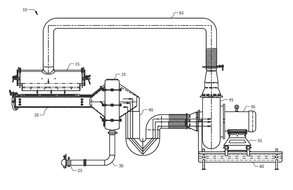
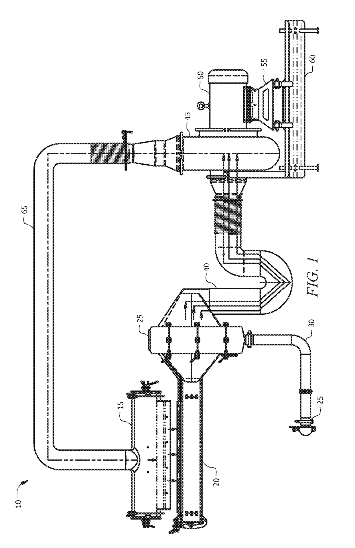
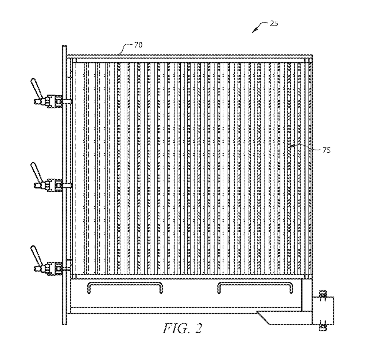
[0019]With reference to FIG. 1, an effluent removal system 10 in accordance with an embodiment of the present invention includes, a vacuum plenum 20 to receive, at an inlet of the vacuum plenum, an effluent mixture comprising a gas and a liquid, a droplet separator 25 having an inlet coupled to an outlet of the vacuum plenum 20, the droplet separator 25 to substantially remove the liquid from the effluent mixture and a blower 45 having an inlet coupled to a gas outlet of the droplet separator 25, the inlet of the blower 45 to receive the gas of the effluent mixture after the liquid has been substantially removed from the effluent mixture by the dr...


PUM

PropertyMeasurementUnit
volumeaaaaaaaaaa
humidityaaaaaaaaaa
pressureaaaaaaaaaa

Abstract

An effluent removal system comprising, a vacuum plenum to receive, at an inlet of the vacuum plenum, an effluent mixture comprising a gas and a liquid, a droplet separator having an inlet coupled to an outlet of the vacuum plenum, the droplet separator to substantially remove the liquid from the effluent mixture and a blower having an inlet coupled to a gas outlet of the droplet separator, the inlet of the blower to receive the gas of the effluent mixture after the liquid has been substantially removed from the effluent mixture by the droplet separator.

Description

FIELD OF THE INVENTION[0001]The present invention relates generally to effluent removal, and more particularly to a food processing vacuum dewatering system that minimizes the possibility of food contamination.BACKGROUND OF THE INVENTION[0002]The Food Safety Modernization Act (FSMA) of 2011 aims to ensure that the United[0003]States food supply is safe by shifting the focus from simply responding to food contamination to proactively preventing the contamination of food. As such, there is a need in the art for hygienically designed food processing equipment that produces microbiologically safe food by minimizing the risk of contamination. It is also desirable that the hygienically designed food processing equipment be easily cleaned and sanitized to further reduce the risk of contamination.[0004]Vacuum dewatering systems are known in the art for removing water or other effluents from a product following a washing process. For example, ready-to-eat (RTE) products, which are common in ...

Claims


Application Information

Patent Timeline
Patent Type & Authority Applications(United States)
IPC IPC(8): B01D45/08
CPCB01D45/08B01D45/16B01D2273/30B01D46/10B01D50/20
Inventor DAVIDSON, ERICK ARTHURGROPPE, RUDI
Owner HEINZEN LLC
Why Eureka
Try Eureka