Nasal assembly

a technology of nasal assembly and spleen, which is applied in the field of nasal assembly, can solve the problems of adversely affecting patient comfort, and prongs irritating the patient's nose, and achieves the effect of more comfort for patients

Active Publication Date: 2011-02-24
RESMED LTD
View PDF22 Cites 71 Cited by
  • Summary
  • Abstract
  • Description
  • Claims
  • Application Information

AI Technical Summary

Benefits of technology

[0018]One aspect of the invention is directed towards a nasal assembly that provides more comfort to the patient.
[0022]Still another aspect of the invention is directed towards a nasal assembly that is easy to use.
[0024]Another aspect is to provide a vent having a profile that is configured to provide improved performance.
[0025]Still another aspect of the invention is directed towards a nasal assembly that helps decouple sealing and stability forces. Specifically, one aspect of the invention is directed towards a nasal assembly that is structured such that the stability forces that act to maintain the nasal assembly on the patient's face are separated or at least better distinguished from the sealing forces that act to maintain a seal between the nasal assembly and the patient's face.
[0026]Yet another aspect of the invention is directed towards a nasal assembly that provides a greater range of movement for nozzles of the nasal assembly.

Problems solved by technology

Thus, adjustment of the fit or stability of the nasal assembly directly affects the seal, which can adversely affect patient comfort.
Similar to Trimble, adjustment of the fit or stability of the nasal assembly directly affects the seal, which can adversely affect patient comfort.
A common problem with known nasal assemblies, such as those discussed above, is patient comfort.
For example, the prongs tend to irritate the patient's nose due to the tension applied by the headgear assembly that pulls the rigid shell and prongs towards the patient's nose.
Another problem is achievement of a sealing fit with the patient's nasal passages without sacrificing patient comfort.
Another problem is irritation of the inside of the patient's nostrils caused by contact with the prongs, e.g., an edge thereof.
Another problem is irritation of the inside of the patient's nostrils caused by air jetting (air flow irritation) from the prongs.
Another problem is adjustment of the nasal assemblies relative to the nose and / or head of the patient so as to accommodate various shapes and angles of patient's noses.
Still another problem is the direct association between sealing and stability forces that can affect patient comfort.

Method used


Image

  • Nasal assembly
  • Nasal assembly
  • Nasal assembly

Examples


Embodiment Construction

[0055]The following includes descriptions of several illustrated embodiments of the present invention. Each illustrated embodiment includes features that may be used with and / or in the other embodiments, or with the embodiments and / or components described in U.S. Non-Provisional application Ser. No. 10 / 781,929, as would be apparent to those of ordinary skill in the art.

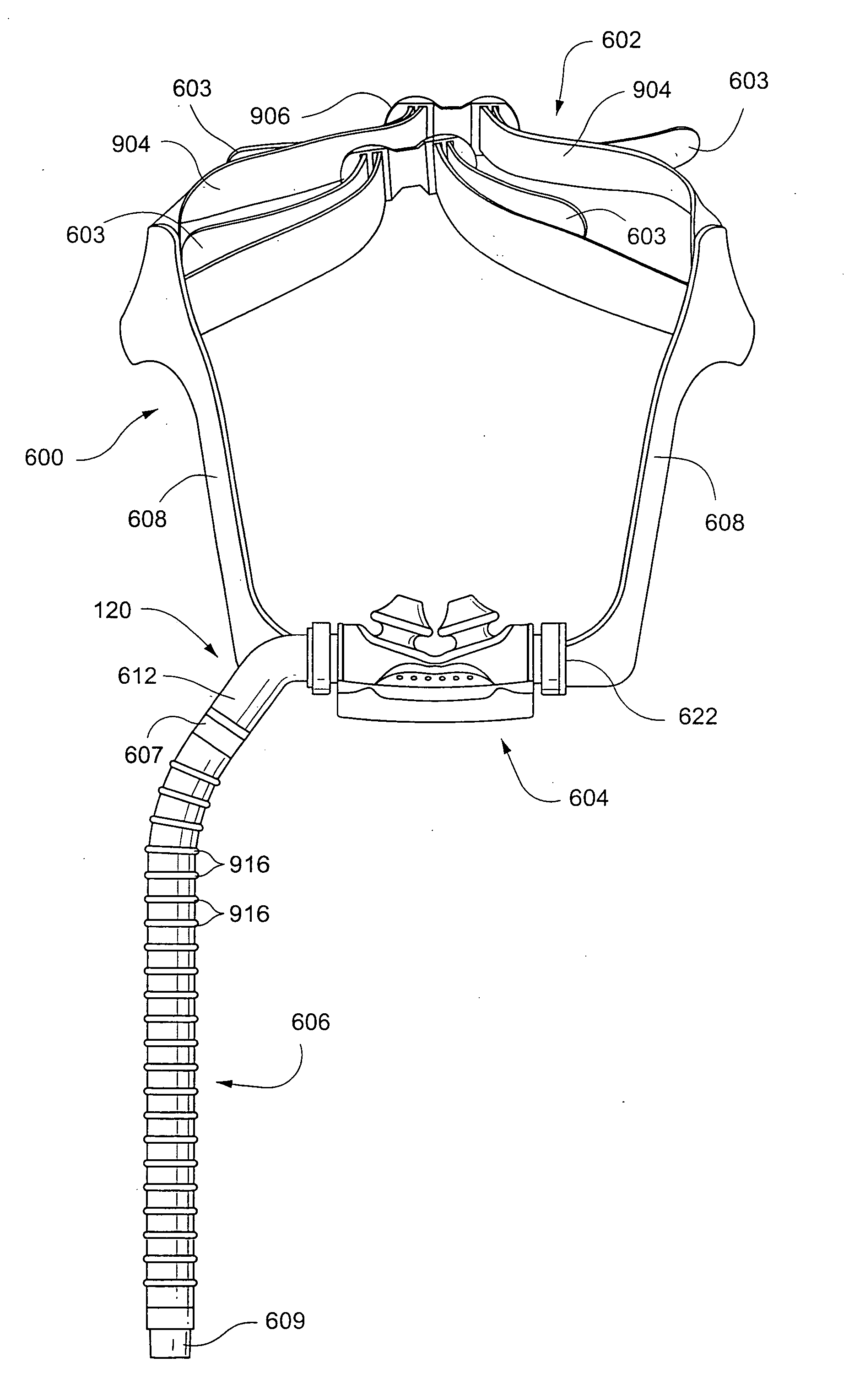
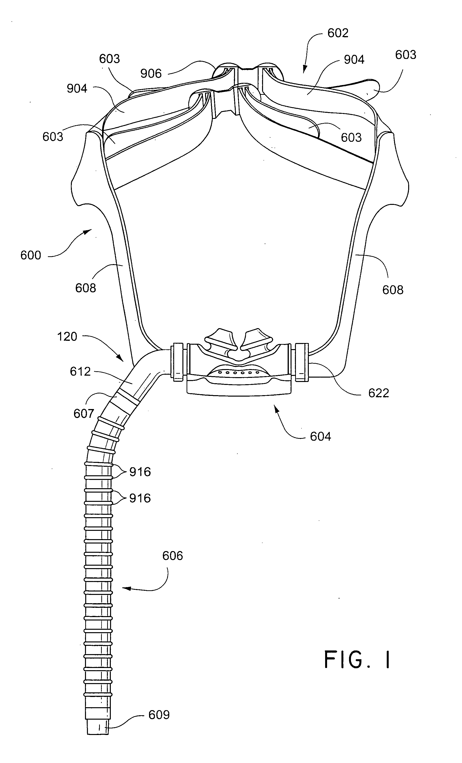
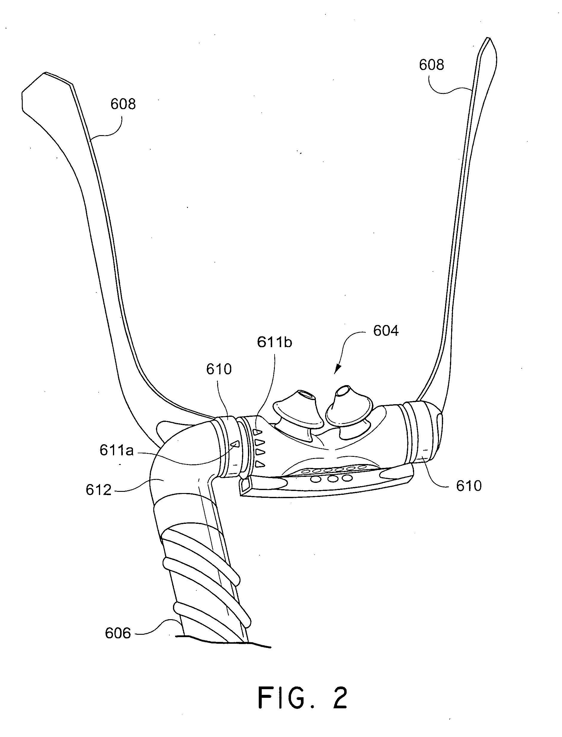
[0056]FIGS. 1-13 illustrate another preferred embodiment of the present invention. As shown in FIG. 1, a mask assembly 600 includes headgear 602 and a cushion assembly 604. Headgear 602 is designed to capture the crown of the patient's head. Adjustment of strap tension can be accomplished by pulling loose tabs 603 on the top of the head in opposite directions. The pulling direction is not aligned with the force the nozzle assembly applies to the patient. Therefore, the patient is more isolated from the strap adjustment forces. Yokes provide stability to the sides. Yokes 608 retain at least a partial portion of the bas...


PUM


Abstract

A nasal assembly for delivering breathable gas to a patient includes a frame having an integrally formed first connector portion. A nozzle assembly includes a gusset or base portion and a pair of nozzles. At least one inlet conduit is structured to deliver breathable gas into the frame and nozzle assembly for breathing by the patient. A pair of second connector portions are removably and rotatably connected to respective first connector portions of the frame and are in communication with respective inlet conduits, e.g., directly or via angle connectors. A headgear assembly is removably connected to the pair of second connector portions and / or the angle connectors so as to maintain the frame and the nozzle assembly in a desired adjusted position on the patient's face.

Description

CROSS-REFERENCE TO APPLICATIONS[0001]This application claims the benefit of U.S. Provisional Application Nos. 60 / 560,610, filed Apr. 9, 2004, and 60 / 632,193, filed Dec. 2, 2004, each incorporated herein by reference in its entirety.FIELD OF THE INVENTION[0002]The present invention relates to a nasal assembly used for treatment, e.g., of Sleep Disordered Breathing (SDB) with Continuous Positive Airway Pressure (CPAP) or Non-invasive Positive Pressure Ventilation (NPPV).BACKGROUND OF THE INVENTION[0003]Some nasal assemblies used in the treatment of SDB are designed for insertion into the nasal passages of the patient. Air or other breathable gas is supplied by a blower and passed along a flexible conduit to the nasal assembly.[0004]The nasal assembly generally includes a relatively rigid shell, e.g., a frame, and a pair of nozzles (which may be in the form of nasal pillows, nasal prongs, cannula, or nasal puffs) that are mounted on the rigid shell and structured to be inserted into th...

Claims


Application Information

Patent Timeline
Patent Type & Authority Applications(United States)
IPC IPC(8): A61M16/06A61M15/08A61M16/08A62B7/00
CPCA61M16/06A61M16/0666A61M16/0683A61M16/0066A61M16/0611A61M16/0825A61M2210/0618
Inventor GUNARATNAM, MICHAEL K.KWOK, PHILIP R.HITCHCOCK, ROBIN G.VELISS, LEE J.GUNEY, MEMDUHSOKOLOV, RICHARDLITHGOW, PERRY D.DARKIN, DONALDLYNCH, SUSAN R.DANTANARAYANA, MUDITHA P.MOORE, RACHEL E.
Owner RESMED LTD
Why Eureka
Try Eureka