Electronic apparatus

Active Publication Date: 2011-02-24
SONY CORP
View PDF22 Cites 23 Cited by
  • Summary
  • Abstract
  • Description
  • Claims
  • Application Information

AI Technical Summary

Benefits of technology

[0030]With this structure, a distance between the bottom surface of the main body portion and the surface on which the main body portion is placed becomes smaller as a distance from the front side of the main body portion decreases. In other words, a distance between the bottom surface of the main body portion and the surface on which the main body portion is placed increases as the distance from the front side of the main body portion increases. As a result, an interference between the first external connector and the surface can be positively prevented from occurring.
[0031]According to another embodiment of the present invention, there is provided an electronic apparatus including a display portion, a main body portion, and a coupling portion. The display portion includes a display screen. The main body portion includes an upper surface and a bottom surface facing each other. The coupling portion couples the display portion with the main body portion such that the display portion becomes rotatable between a first state where the display screen faces the upper surface and a second state where the display screen forms a predetermined angle with respect to the upper surface. The main body portion includes a pair of side surfaces that are orthogonal to the bottom surface and face each other, a second connector that is provided on one of the pair of side surfaces while being connectable with a second external connector and includes a terminal portion provided on the side surface as one of the pair of side surfaces in an exposable state to be connected to the second external connector, and a cover that is rotatable with the bottom surface side as a fulcrum so that the terminal portion of the second connector is opened and closed. The display portion includes a first leg portion that protrudes to

Problems solved by technology

However, in recent years, thinning of such a laptop PC is progressing.
Since the leg member described above has a structure that does not take the thickness of the connector po

Method used


Image

  • Electronic apparatus
  • Electronic apparatus
  • Electronic apparatus

Examples


Embodiment Construction

[0081]Hereinafter, an embodiment of the present invention will be described with reference to the drawings.

[0082](Structure of Electronic Apparatus)

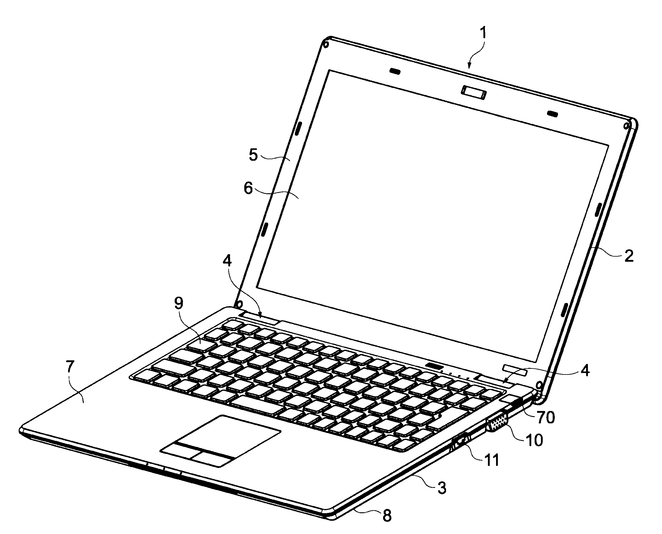
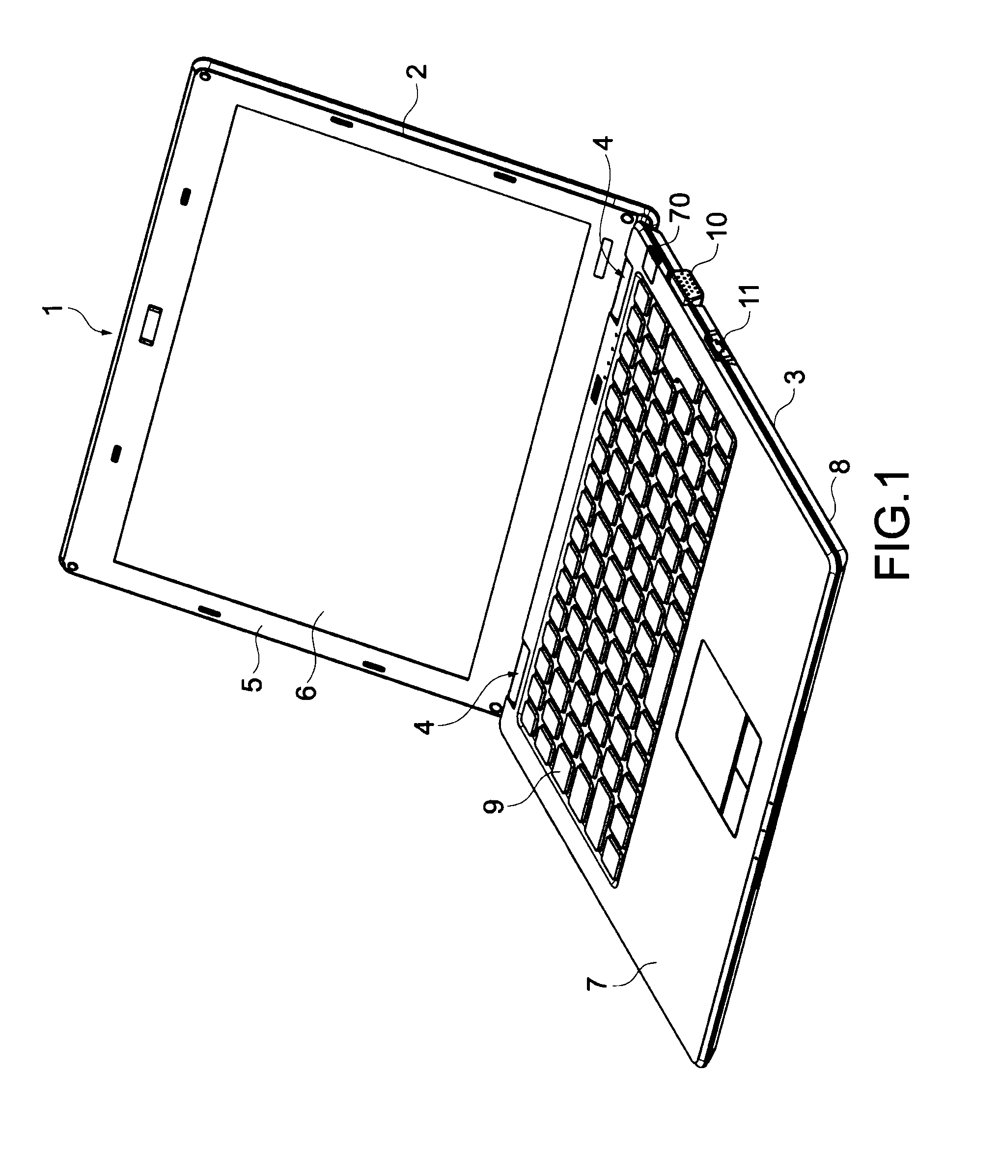
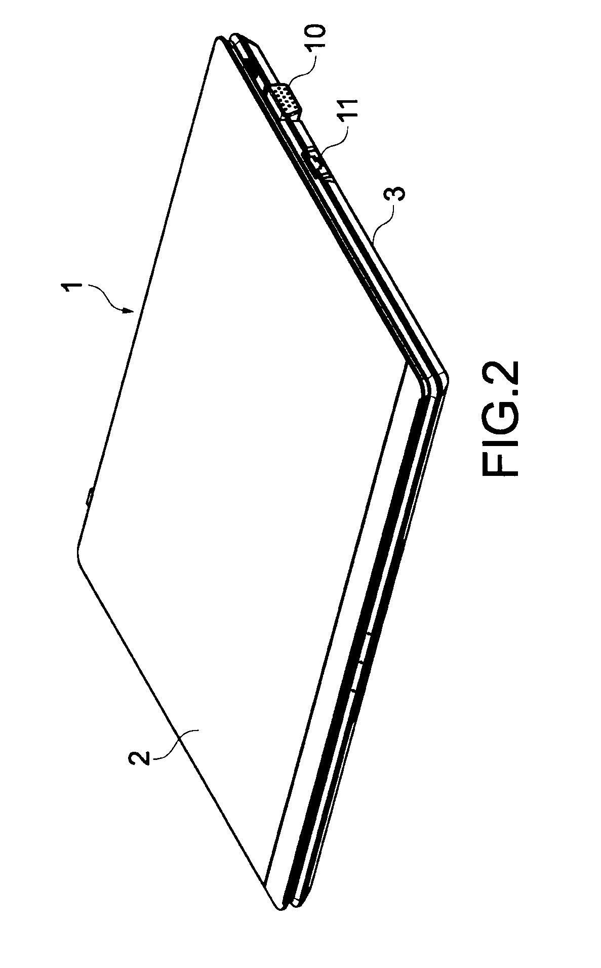
[0083]FIG. 1 is a perspective view showing a state where an electronic apparatus 1 according to an embodiment of the present invention is opened, and FIG. 2 is a perspective view showing a state where the electronic apparatus 1 shown in FIG. 1 is closed (first state).

[0084]The electronic apparatus 1 includes a display portion 2, a main body portion 3, and coupling portions 4 that rotatably couple the display portion 2 with the main body portion 3.

[0085]The display portion 2 can be opened and closed with respect to the main body portion 3 via the coupling portions 4. The display portion 2 includes a casing 5 of the display portion 2, a display screen 6, and an LCD (Liquid Crystal Display) display panel (not shown) that is provided inside the casing 5 for performing display processing.

[0086]The casing 5 is an exterior component of the disp...


PUM


Abstract

An electronic apparatus includes: a display portion including a display screen; a main body portion including upper and bottom surfaces; and a coupling portion to couple the display portion with the main body portion such that the display portion becomes rotatable between a first state where the display screen faces the upper surface and a second state where the display screen forms a predetermined angle with respect to the upper surface, the main body portion including a pair of side surfaces, and a first connector connectable with a first external connector and includes a lower surface exposed from the bottom surface, the display portion including a first leg portion that protrudes to be positioned lower than the bottom surface in the second state and comes into contact with a surface on which the main body portion is placed to form a predetermined tilt with respect to the surface.

Description

BACKGROUND OF THE INVENTION[0001]1. Field of the Invention[0002]The present invention relates to an electronic apparatus such as a foldaway laptop personal computer.[0003]2. Description of the Related Art[0004]From the past, an electronic apparatus such as a foldaway laptop personal computer (hereinafter, referred to as PC) is equipped with a main body portion including a keyboard and a display portion that is rotatably coupled with the main body portion. A connector to which a connector portion provided at one end of an information communication cable is connected is provided on a side surface of the main body portion, and a leg member for placing the electronic apparatus on a desk or the like while tilting the keyboard is provided on a bottom surface of the main body portion of the electronic apparatus while being rotatable with respect to the main body portion (see, for example, Japanese Patent Application Laid-open No. Hei 5-119885 (paragraphs [0006] and [0007], FIGS. 2 and 3))....

Claims


Application Information

Patent Timeline
IPC IPC(8): H05K5/00
CPCG06F1/1616G06F1/1656G06F1/1613G06F1/1671H01R2201/06G06F1/166
Inventor SAITO, KENJIWATABE, MANABUNAKAMURA, TAKASHINAKAGAWA, KAZUTO
Owner SONY CORP
Why Eureka
Try Eureka