Dental pliers

Inactive Publication Date: 2011-02-24
GOODMAN PHILLIP MARSHALL
View PDF7 Cites 14 Cited by
  • Summary
  • Abstract
  • Description
  • Claims
  • Application Information

AI Technical Summary

Benefits of technology

[0007]It is an object t

Problems solved by technology

One problem particularly troublesome to dentists is the failure of such pliers to provide dental pliers capable of cleanly removing a band connected to a tooth surface in a manner without driving the band under th

Method used


Image

  • Dental pliers
  • Dental pliers
  • Dental pliers

Examples


Embodiment Construction

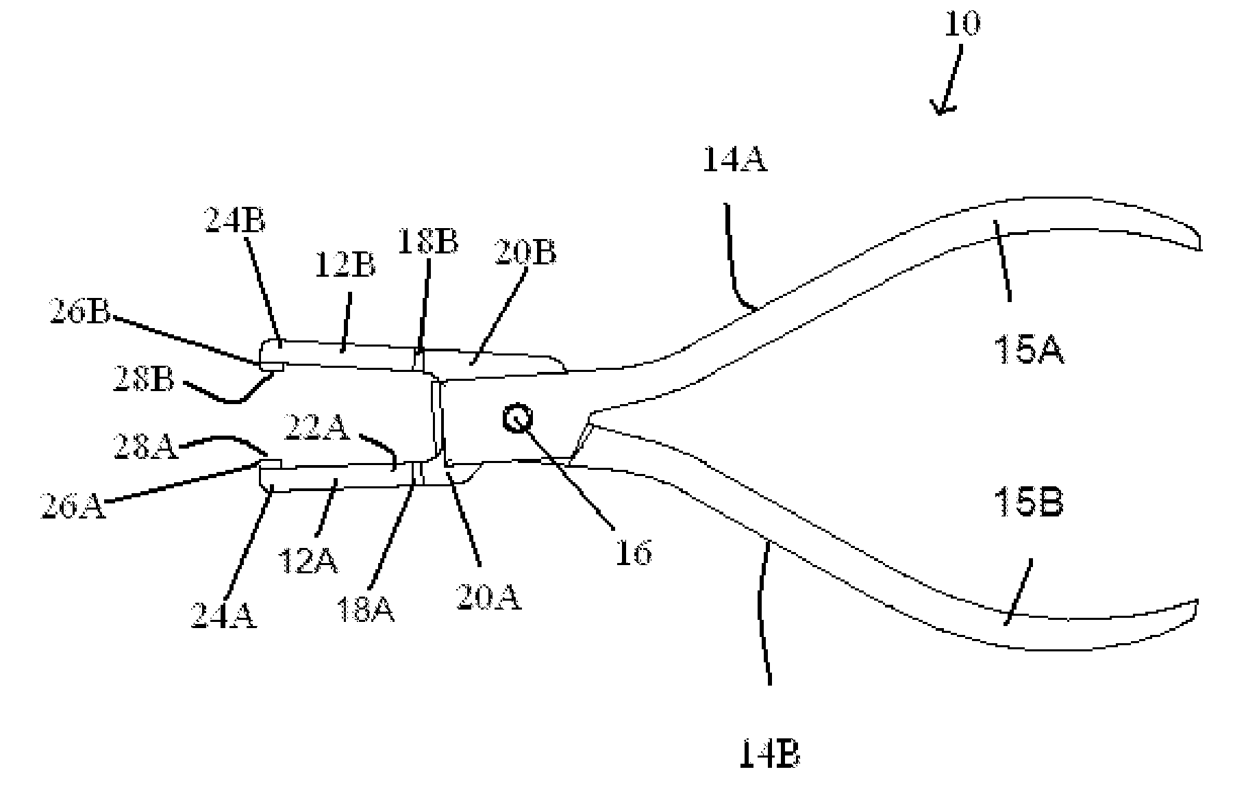
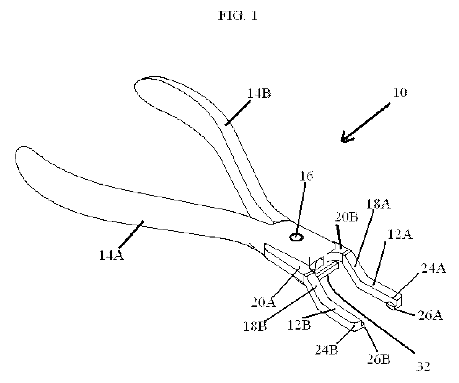
[0026]Referring now to FIG. 1, dental pliers of the present invention is generally designated by the numeral 10. The preferred material for the construction of the pliers 10 is surgical stainless steel, except for parts otherwise discussed hereinafter. This permits pliers 10 to be sterilized via an autoclave.

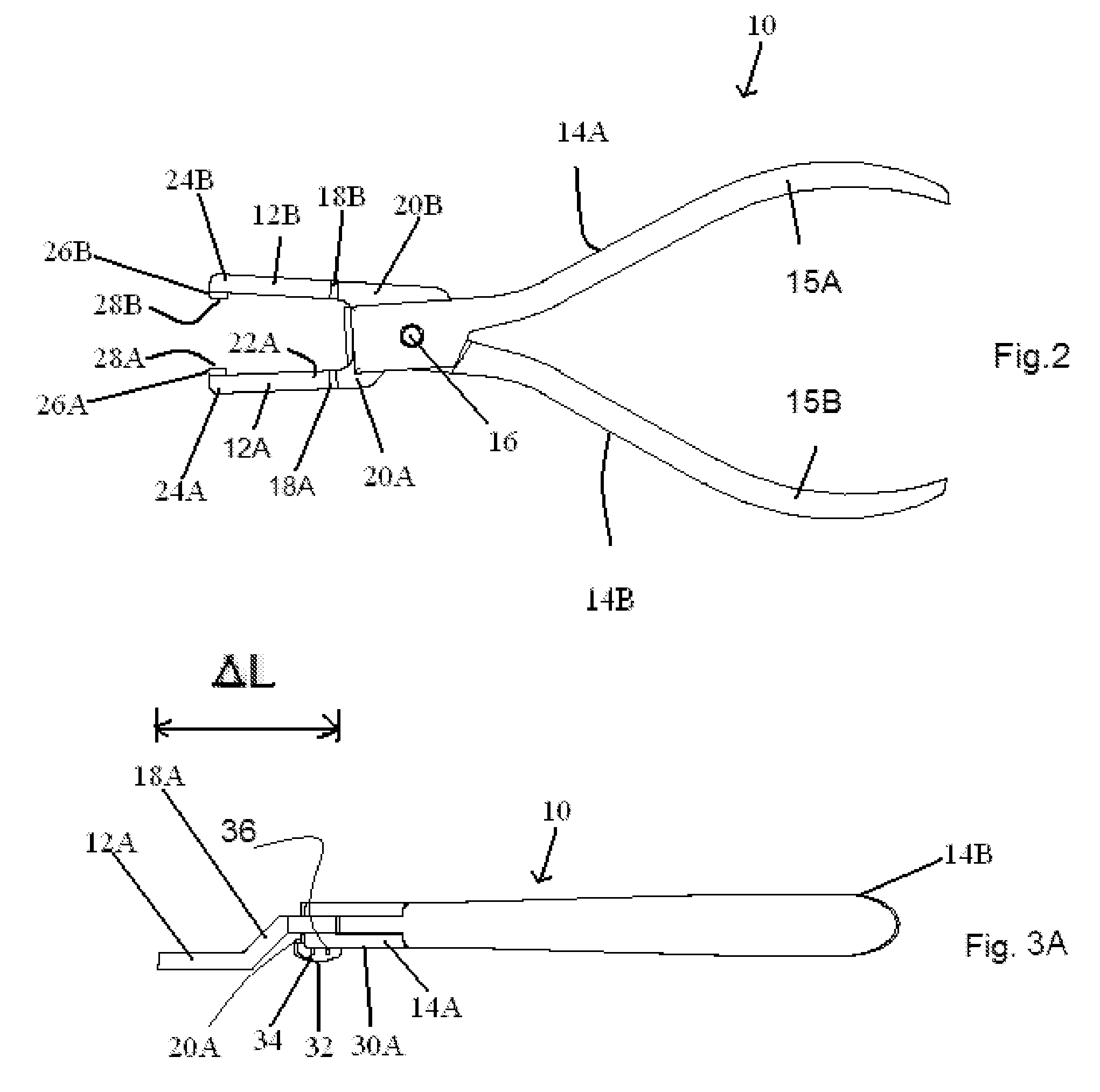
[0027]The dental pliers 10 has a pair of opposing jaw parts, 12A and 12B, which generally lie in a first plane P and are each connected to an arm 14A and 14B, respectively, which lie generally outside the first plane P. Each of the arms, 14A and 14b, can preferably be curved at rearward end 15A and 15B to aid in handling the pliers 10. The arms 14A and 14B are pivotally connected about a pivot pin 16 in a manner such that when the jaws 12A and 12B are displaced from / restored toward each other as the arms 14A and 14b are displaced from / restored toward each other.

[0028]Interconnecting each jaw 12A-arm14A and jaw 12B-arm14B pair is an angle portion 18A and 18b, respectively. The an...


PUM


Abstract

A dental pliers includes a pair of opposing jaw parts which generally lie in a first plane, a pair of arms each connected to one of the jaw parts and wherein the arms lie generally outside the first plane, wherein the arms are pivotally connected in a manner such that the jaws are displaced from/restored toward each other as the arms are displaced from/restored toward each other, and a pad connected to at least one of the arms extending toward the first plane.

Description

BACKGROUND OF THE INVENTION[0001]1. Field of Invention[0002]The present invention relates generally to improved methods and devices for the removal of dental prostheses, such as dental bands and crowns, as well as baby teeth. Traditional methods for the removal of dental crowns include those such as the following.[0003]2. Prior Art[0004]Prior pliers, or other like devices, have been designed for handling dental prostheses. One problem particularly troublesome to dentists is the failure of such pliers to provide dental pliers capable of cleanly removing a band connected to a tooth surface in a manner without driving the band under the gum tissue.[0005]Similarly, the art lacks one dental plier capable of performing multiple functions: i.e. removal of temporary crowns, removal of orthodontic bands, and removal of teeth, particularly loose baby teeth. Prior to this instrument, three separate instruments would be necessary to accomplish the aforementioned tasks.[0006]Accordingly, a denta...

Claims


Application Information

Patent Timeline
IPC IPC(8): A61C3/14A61C3/16
CPCA61C3/162A61C3/14
Inventor GOODMAN, PHILLIP MARSHALL
Owner GOODMAN PHILLIP MARSHALL
Why Eureka
Try Eureka