Knee exerciser

a knee exerciser and knee technology, applied in the field of knee exercisers, can solve the problems of increasing the difficulty of exercise, increasing the knee angle, reflexively withdrawing users from the motion, etc., and achieves the effects of flexing a joint, reducing pain, and controlling the range and speed of flexing

Inactive Publication Date: 2011-02-24
STILES MICHELLE
View PDF1 Cites 3 Cited by
  • Summary
  • Abstract
  • Description
  • Claims
  • Application Information

AI Technical Summary

Benefits of technology

[0010]In operation, a user places the ball of his or her foot on the middle of the cross-member. The user then places both hands on the handle portion of the U-shaped bar, or along the straight portion of the U-shaped bar proximate the handle portion, or in another embodiment on the straight, opposing ends forming a handle portion of the H-shaped device. The user then slowly pulls the handle portion toward his or her knee until the knee is properly stretched. The proper stretch is a moderate intensity stretch wherein the user will feel some discomfort and a pulling feeling in the knee. Stretching too far will cause pain and the user to reflexively withdraw from the motion. Position of the cross-member is adjusted using a pair of threaded knobs. The position of the cross-member impacts the excursion of the foot backward and hence the bend in the knee. Raising the height of the cross-member (i.e. from proximate the terminus of the distal ends and closer to the floor, to closer to the handle end and further from the floor) increases the difficulty of the exercise by increasing the knee angle if the distance of the device from the user remains constant. Alternatively, the user can increase the knee angle by “walking” the device closer to his or her body. “Walking” entails the user lifting one distal end and replacing it on the floor closer to his or her body. He or she then repeats the process on the other distal end. Preferably, the user “walks” the device a distance equal to the width of the distal end portion of the U-shaped bar or H-shaped device. When a user is able to easily pull the handle to his or her knee, it is time to “walk” the device closer to the body. “Walking” the device allows the user to maintain the continuity of the exercise and increase the difficulty without the added need of having to change the cross-member height.
[0011]The knee flexing device according to the present invention is formed preferably as a steel or metal member which is U-shaped, having a curved or squared end serving as a handle portion and having two distal ends. The U-shaped steel member is preferably formed from hollow tubing having an outer diameter which has preferably been selected from a range of from one-half inch to one inch in diameter. The two distal ends are equipped with anti-slipping members, preferably rubber feet or a pivoting foot having a rubber base. A cross-member is adjustably positioned between the distal ends of the U-shaped steel member. Although the cross-member can have any cross sectional shape, including but not limited to round, oval, hexagonal, or triangular, the preferred shape is square. The cross-member is preferably formed from square hollow tubing which has preferably been selected from a range of one-half inch to one inch. The cross-member is preferably coated with a non-slip surface to prevent a user's foot from slipping off of the cross-member during use. The square shaped cross-member is adjustably affixed to the U-shaped member through a pair of round tubular attachments. The round tubular attachment is preferably formed from hollow steel tubing having an inner diameter sufficient to fit snuggly around the distal ends of the U-shaped member. The cross-member is permanently affixed to the round tubular attachments, preferably by a weld. A hole is drilled through the side of the round tubular attachment opposite the connection point of the cross-member. A steel nut is welded to the attachment such that the threaded hole of the nut is in communication with the drilled hole on the attachment. A bolt having a user-friendly knob is threaded into the welded nut. When tightened into the nut, the bolt applies pressure to the outer wall of the U-shaped member. The applied pressure holds the cross-member in place and prevents it from slipping when in use.
[0012]In another embodiment, the device is roughly H-shaped. The handle portion of the U-shaped bar of the earlier embodiment is replaced with two opposing handles. The handles form the upright of the H-shape. The opposing handles can be parallel with one another or positioned so that they are leaning toward one another to increase user comfort and ease. The two parallel members of the H-shaped device are preferably formed of hollow tubing steel or metal having an outer diameter which has preferably been selected from a range of from one-half inch to one inch in diameter. The two distal ends which rest on the floor during use are equipped with anti-slipping members, preferably rubber feet or a pivoting foot having a rubber base. The handle portions of the upright ends of the parallel members are equipped with improved gripping material such as rubber, formed plastic, or by having an etched surface. A cross-member is adjustably positioned between the parallel members of the H-shaped steel device. Although the cross-member can have any cross sectional shape, including but not limited to round, oval, hexagonal, or triangular, the preferred shape is square. The cross-member is preferably formed from square hollow tubing which has preferably been selected from a range of one-half inch to one inch. The cross-member is preferably coated with a non-slip surface to prevent a user's foot from slipping off of the cross-member during use. The square shaped cross-member is adjustably affixed to the parallel H-shaped members through a pair of round tubular attachments. The round tubular attachment is preferably formed from hollow steel tubing having an inner diameter sufficient to fit snuggly around the distal ends of the H-shaped members. The cross member is permanently affixed to the round tubular attachments, preferably by means of a weld. A hole is drilled through the side of the round tubular attachment opposite the connection point of the cross-member. A steel nut is welded to the attachment such that the threaded hole of the nut is in communication with the drilled hole on the attachment. A bolt having a user-friendly knob is threaded into the welded nut. When tightened into the nut, the bolt applies pressure to the outer wall of the H-shaped members. The applied pressure holds the cross-member in place and prevents it from slipping when in use.
[0014]Yet another object of the present invention is to provide a post-surgery exercise device which is easy and inexpensive to manufacture and use. Still another object of the present invention is to provide a post-surgery exercise device which is adjustable for different user sizes, strengths, and flexion abilities.
[0015]Yet still another object of the present invention is to provide a post-surgery exercise device for flexing a joint with the ability to control the range and speed of the flexing.

Problems solved by technology

Stretching too far will cause pain and the user to reflexively withdraw from the motion.
Raising the height of the cross-member (i.e. from proximate the terminus of the distal ends and closer to the floor, to closer to the handle end and further from the floor) increases the difficulty of the exercise by increasing the knee angle if the distance of the device from the user remains constant.

Method used


Image

  • Knee exerciser
  • Knee exerciser
  • Knee exerciser

Examples


Embodiment Construction

[0024]At the outset, it should be clearly understood that like reference numerals are intended to identify the same structural elements, portions, or surfaces consistently throughout the several drawing figures, as may be further described or explained by the entire written specification of which this detailed description is an integral part. The drawings are intended to be read together with the specification and are to be construed as a portion of the entire “written description” of this invention as required by 35 U.S.C. §112.

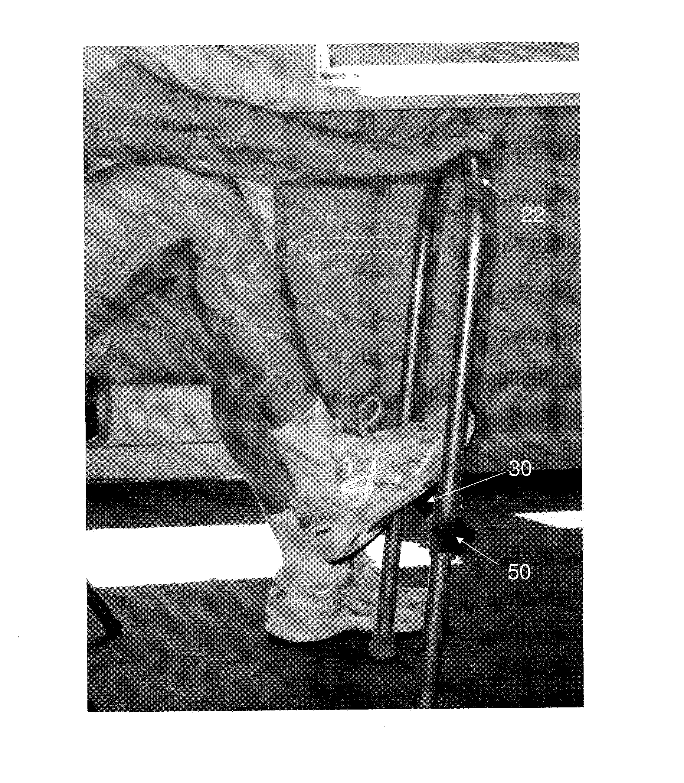
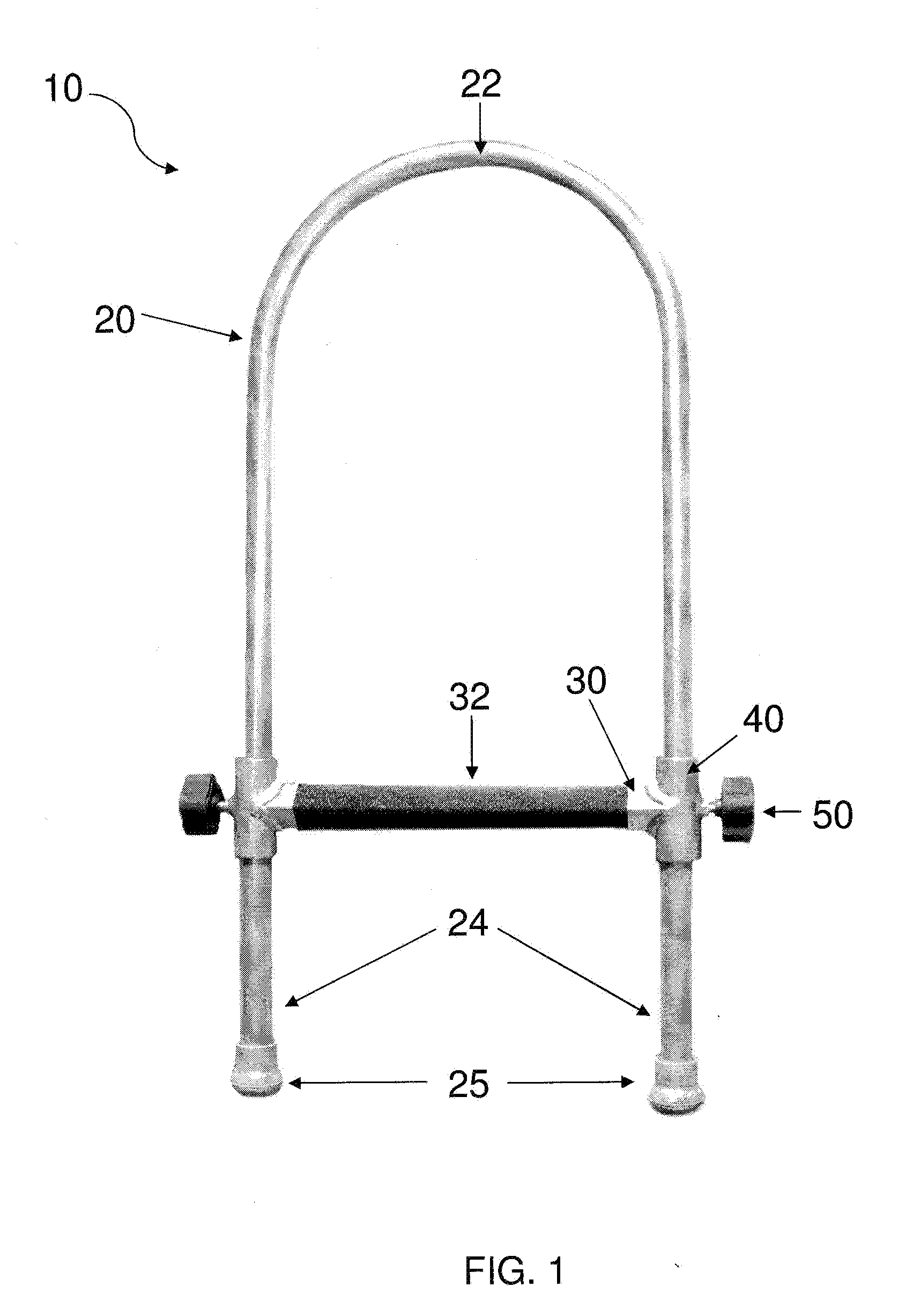
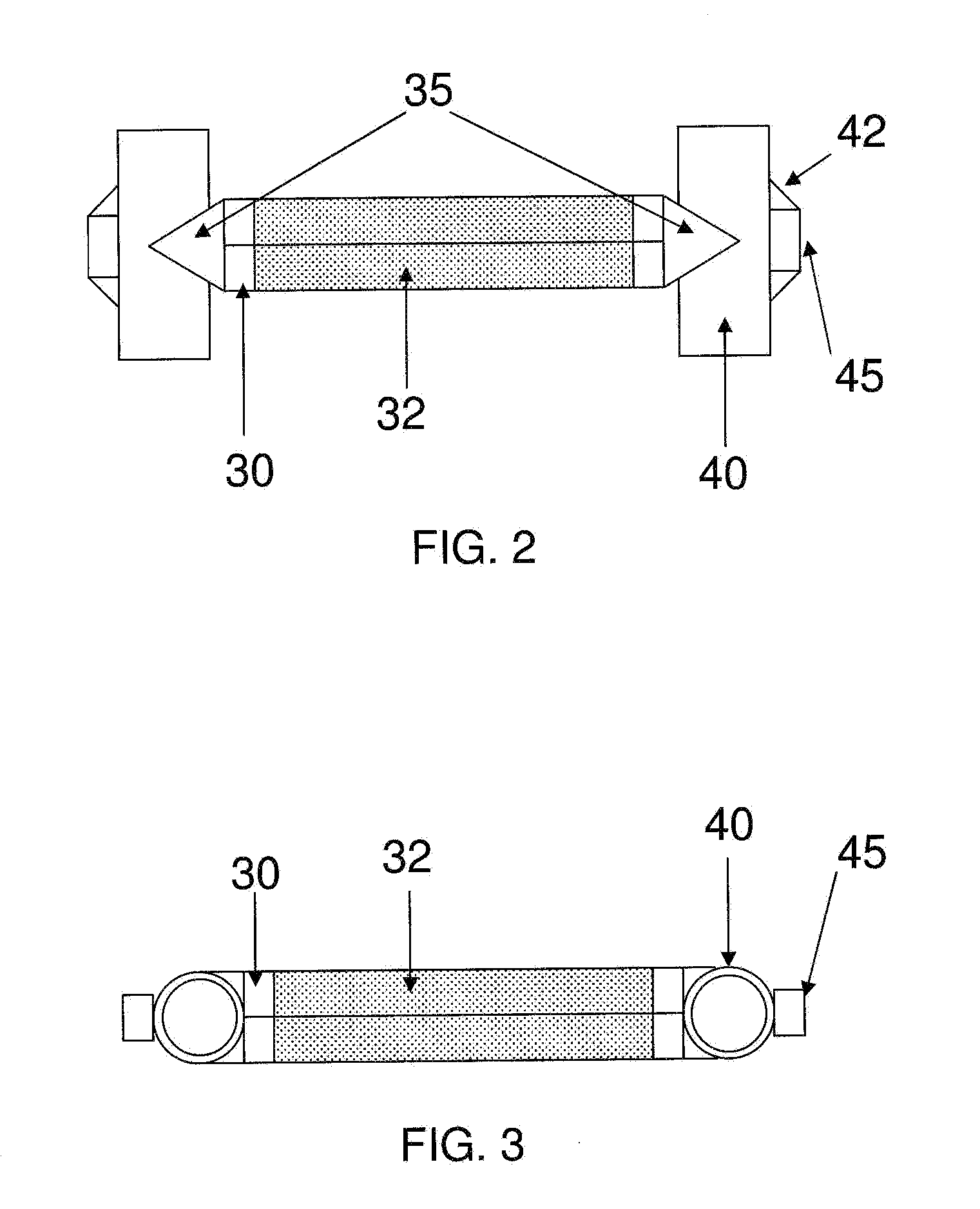
[0025]A knee flexing device of the present invention is shown in FIG. 1. The knee flexing device 10 may include a U-shaped bar 20 having a curved or squared end 22 which may serve as a handle portion and may have two distal ends 24 which may be placed on the floor during use. The U-shaped bar 20 may have a first and a second armed portion which may be connected to a base portion. A cross-member 30 which may be square shaped may be positioned perpendicular to...


PUM


Abstract

An apparatus for flexing the knee comprising a U-shaped bar having two straight arms each having a distal end and a handle portion generally perpendicular to the straight arms and a perpendicular cross-member adjustably attached to the straight arms; and a method for flexing the knee comprising the steps of providing a patient with device having a handle section and two parallel straight sections with a perpendicular cross-member attached to the straight sections, having the patient to place his or her foot onto the cross-member, and having the patient to pull the device toward the knee.

Description

PRIORITY[0001]The present invention claims priority under 35 USC section 119 and is based on a provisional application which was filed on Aug. 19, 2009 with a serial number of 61 / 235,066FIELD OF THE INVENTION[0002]This invention relates generally to the fields of physical therapy and patient rehabilitation and, more specifically to physical therapy devices and methods for the knee.BACKGROUND[0003]Over one half million total knee replacement (TKR) surgeries are performed in the United States every year. This number is expected to grow to over three-and-a-half million surgeries by the year 2030. In recent years, significant progress has been made in the surgical procedure, surgical components, and approaches to rehabilitation. Initially, TKR patients were immobilized for 4 to 6 weeks following surgery because it was feared that early range of motion (ROM) movements would be harmful to the new joint. The result, however, was that regaining full ROM was extremely difficult after the kne...

Claims


Application Information

Patent Timeline
Patent Type & Authority Applications(United States)
IPC IPC(8): A61H1/02
CPCA61H1/024
Inventor STILES, MICHELLE
Owner STILES MICHELLE
Why Eureka
Try Eureka