Reaction chamber

A reaction chamber and cavity technology, applied in the field of reaction chambers, can solve the problems of shortening the service life of the first sealing ring 10 and the second sealing ring 13, so as to reduce the quantity, reduce the risk of metal contamination, and improve the service life Effect

Active Publication Date: 2018-10-23
BEIJING NAURA MICROELECTRONICS EQUIP CO LTD
View PDF7 Cites 0 Cited by
  • Summary
  • Abstract
  • Description
  • Claims
  • Application Information

AI Technical Summary

Problems solved by technology

[0005] First, the first sealing ring 10 and the second sealing ring 13 are in direct contact with the process gas environment through the first gap 11 and the second gap 12 respectively, and the two are bombarded by plasma for a long time, resulting in the first sealing ring 10 and the second sealing ring 13 being in direct contact with the process gas environment. The service life of the second sealing ring 13 is reduced

Method used


Image

  • Reaction chamber
  • Reaction chamber
  • Reaction chamber

Examples


Embodiment Construction

[0057] In order to enable those skilled in the art to better understand the technical solution of the present invention, the reaction chamber provided by the present invention will be described in detail below with reference to the accompanying drawings.

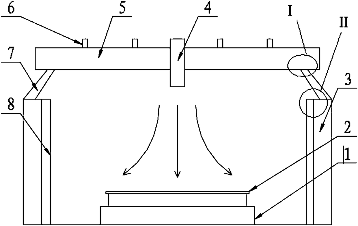
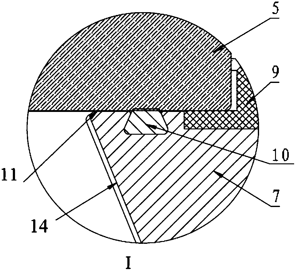
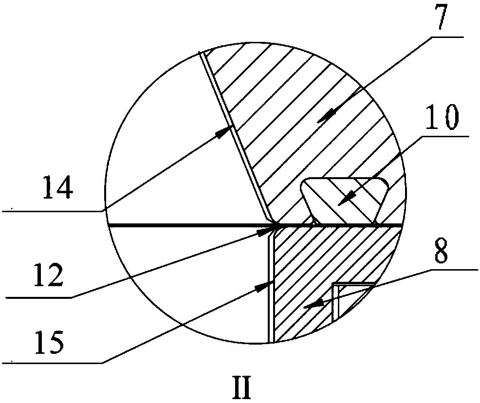
[0058] Figure 4A A cross-sectional view of the reaction chamber provided by the first embodiment of the present invention. Figure 4B for Figure 4A Enlarged view of region A in the middle. Figure 4C for Figure 4A Enlarged view of region B in the middle. Please also refer to Figure 4A ~ Figure 4B , the reaction chamber includes a chamber 21 , an adjustment bracket 25 and a dielectric window 29 arranged in sequence from bottom to top, wherein a base 32 is provided inside the chamber 21 for carrying a wafer 33 . A gas inlet nozzle 31 is provided in the dielectric window 29 to deliver the process gas to the inside of the cavity 21, and a radio frequency coil 30 is provided above the dielectric window 29 to excite the p...


PUM


Abstract

The invention provides a reaction chamber, which comprises a cavity, an adjustment bracket, a medium window, an upper protective ring and a lower protective ring, wherein the upper surface of the adjustment bracket and the lower surface of the medium window are provided with a first clearance therebetween, and the first clearance is internally provided with a first sealing ring; the lower surfaceof the adjustment bracket and the upper surface of the cavity are provided with a second clearance therebetween, and the second clearance is internally provided with a second sealing ring; the upper protective ring is installed at the inner side of the adjustment bracket, a third clearance is formed between the upper protective ring and two opposite surfaces of the medium window so as to be used for prolonging the distance between the first clearance and an internal space of the cavity; and the lower protective ring is installed at the inner side of the cavity, a fourth clearance is formed between the lower protective ring and two opposite surfaces of the adjustment bracket so as to be used for prolonging the distance between the second clearance and the internal space of the cavity. The reaction chamber provided by the invention not only can reduce the risk of generating metal pollution, but also can avoid direct exposure of the sealing ring in a plasma environment.

Description

technical field [0001] The present invention relates to the technical field of semiconductor manufacturing, in particular to a reaction chamber. Background technique [0002] For the current plasma processing equipment, the plasma is formed in the reaction chamber and is close to the lower surface of the dielectric window. Since the plasma has high energy, it has a great influence on the parts around the dielectric window. With the continuous update of the integrated circuit manufacturing process, it is necessary to improve the equipment structure to reduce the source of metal pollution, and the control ability of metal pollution has become an important indicator of the process extension of the machine. [0003] figure 1 It is a structural diagram of an existing reaction chamber. like figure 1 As shown, the reaction chamber includes a cavity 3, an adjustment bracket 7 and a dielectric window 5 arranged sequentially from bottom to top, wherein a base 1 is provided in the c...

Claims


Application Information

Patent Timeline
Patent Type & Authority Applications(China)
IPC IPC(8): H01J37/32
CPCH01J37/32431H01J37/32458H01J37/32477H01J37/32513H01J37/32798
Inventor 黄亚辉李一成刘建
Owner BEIJING NAURA MICROELECTRONICS EQUIP CO LTD
Why Eureka
Try Eureka