
Shoe positioning device of a bicycle

a positioning device and bicycle technology, applied in the direction of bicycle components, mechanical devices, footwear, etc., can solve the problems of injury or life-threatening accidents of cyclists, difficulty in detachment, and relatively high production costs, and achieve the effect of quick engagement and disengagement from the sole of the bicycl

Inactive Publication Date: 2011-03-03
HOPE IND
View PDF10 Cites 6 Cited by
  • Summary
  • Abstract
  • Description
  • Claims
  • Application Information

AI Technical Summary

Benefits of technology

[0010]The objective of the present invention is to provide a shoe positioning device of a bicycle that can be quickly engaged and disengaged from a cyclist's sole.
[0016]The shoe positioning device of a bicycle of the present invention at least has the following advantages and benefits:
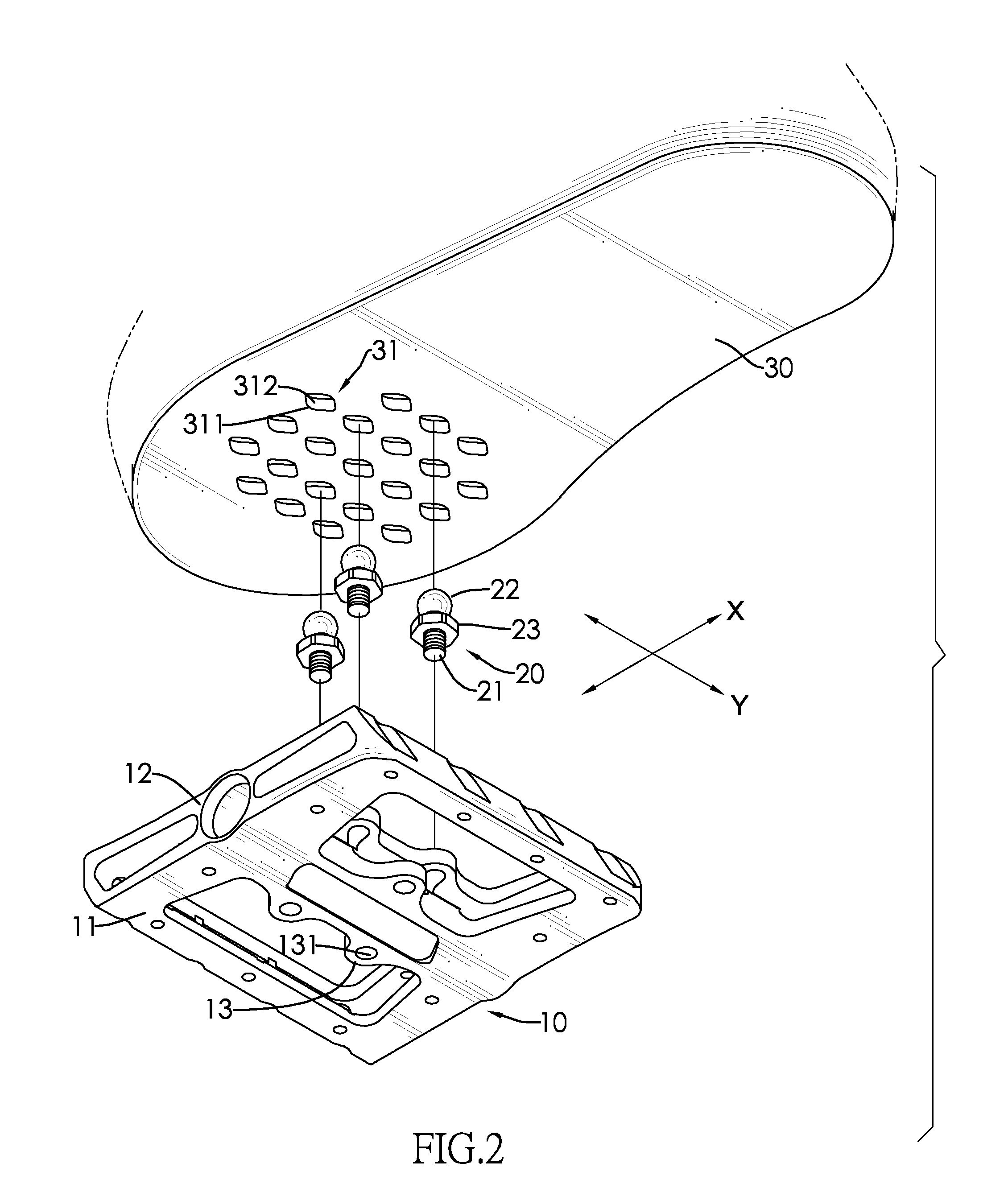
[0017]1. In view of the first and second widths being smaller than the third and fourth widths, the locating block of one of the positioning elements can be received and positioned in a corresponding locating recess. Hence, the shoes of a cyclist can be positioned on the pedals. Since the first width is smaller than the second width of the bottom opening of each locating recess, the positioning element received in the locating recess can only be moved forwards and backwards upon cycling and is firmly positioned in the locating recess. When the sole of a shoe is required to pull out from the positioning element, cyclist just needs to move the shoe to the left or to the right and tilt the sole with respect to a horizontal plane to promptly pull out from the locating recess, thereby reducing chances of injury and life-threatening risks in an accident.
[0018]2. The shoe positioning device of the present invention has multiple locating recesses formed in the soles of a pair of shoes. Such shoes can be used for normal walking. Cyclists do not need to prepare an additional pair of shoes for walking after cycling, thereby providing bicycle outfits with more practical value.
[0019]3. The shoe positioning device of the present invention has a simple structure and composition of parts in favor of production, assembly and cost so as to further increase competitive edge of products of the present invention in the market.

Problems solved by technology

1. Although the rib 91 and the wings 92 secure the engagement of the pedal 80 and the shoe locator 90, the shoe locator 90 is difficult to detach from the pedal 80. This issue could cause injuries or life-threatening accidents to cyclists if they encounter a dangerous situation and not being able to jump off the bicycle.
2. Because the shoe locator 90 is mounted on and protrudes from a bottom of a shoe, the shoe having the shoe locator 90 is dedicated to cycling instead of regular walking. Consequently, cyclists need to change shoes when they want to take a walk, which is inconvenient.
3. The conventional shoe positioning device comprises many parts. Therefore, production costs are relatively high as more labor hours and materials are needed to produce the conventional shoe positioning device.

Method used


Image

  • Shoe positioning device of a bicycle
  • Shoe positioning device of a bicycle
  • Shoe positioning device of a bicycle

Examples


Embodiment Construction

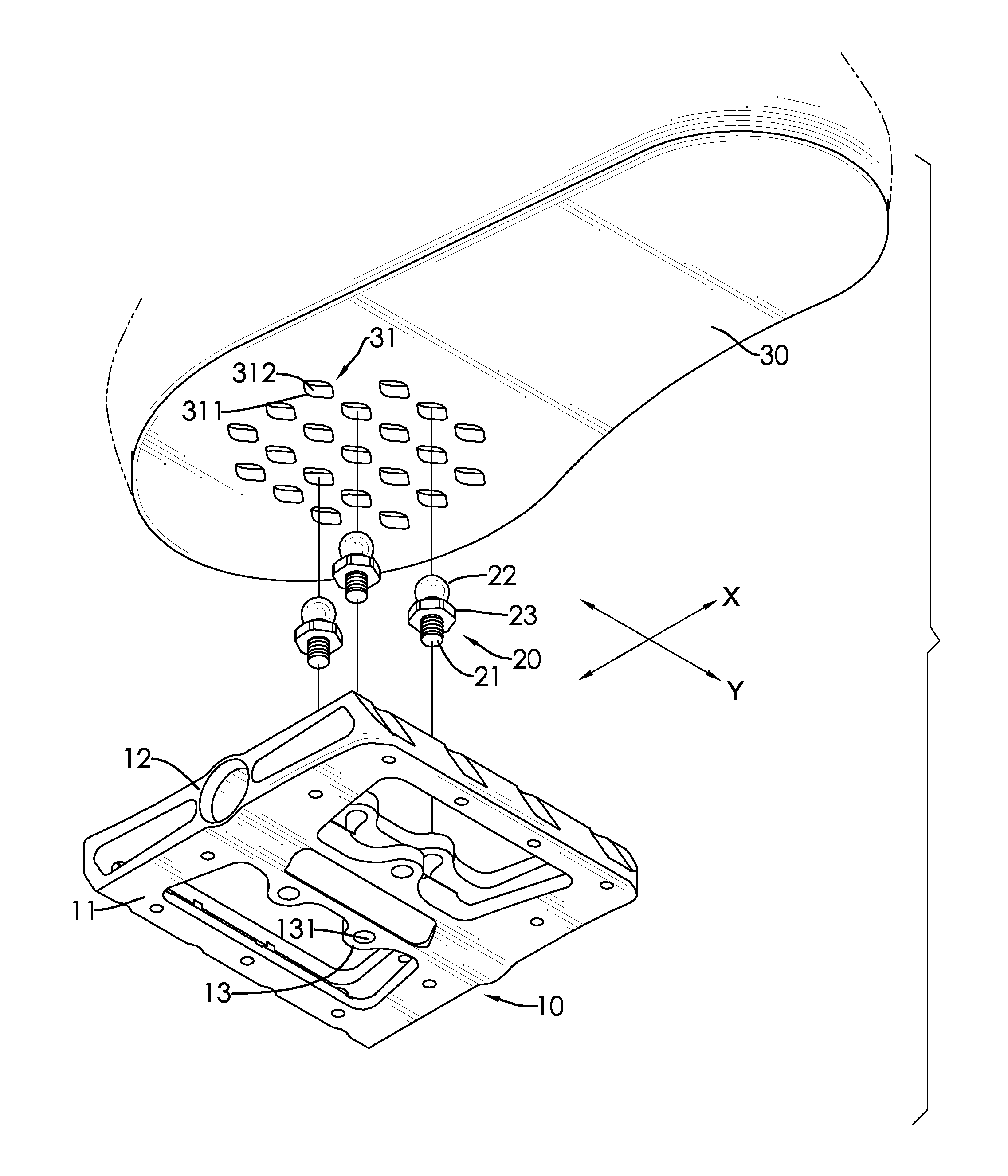
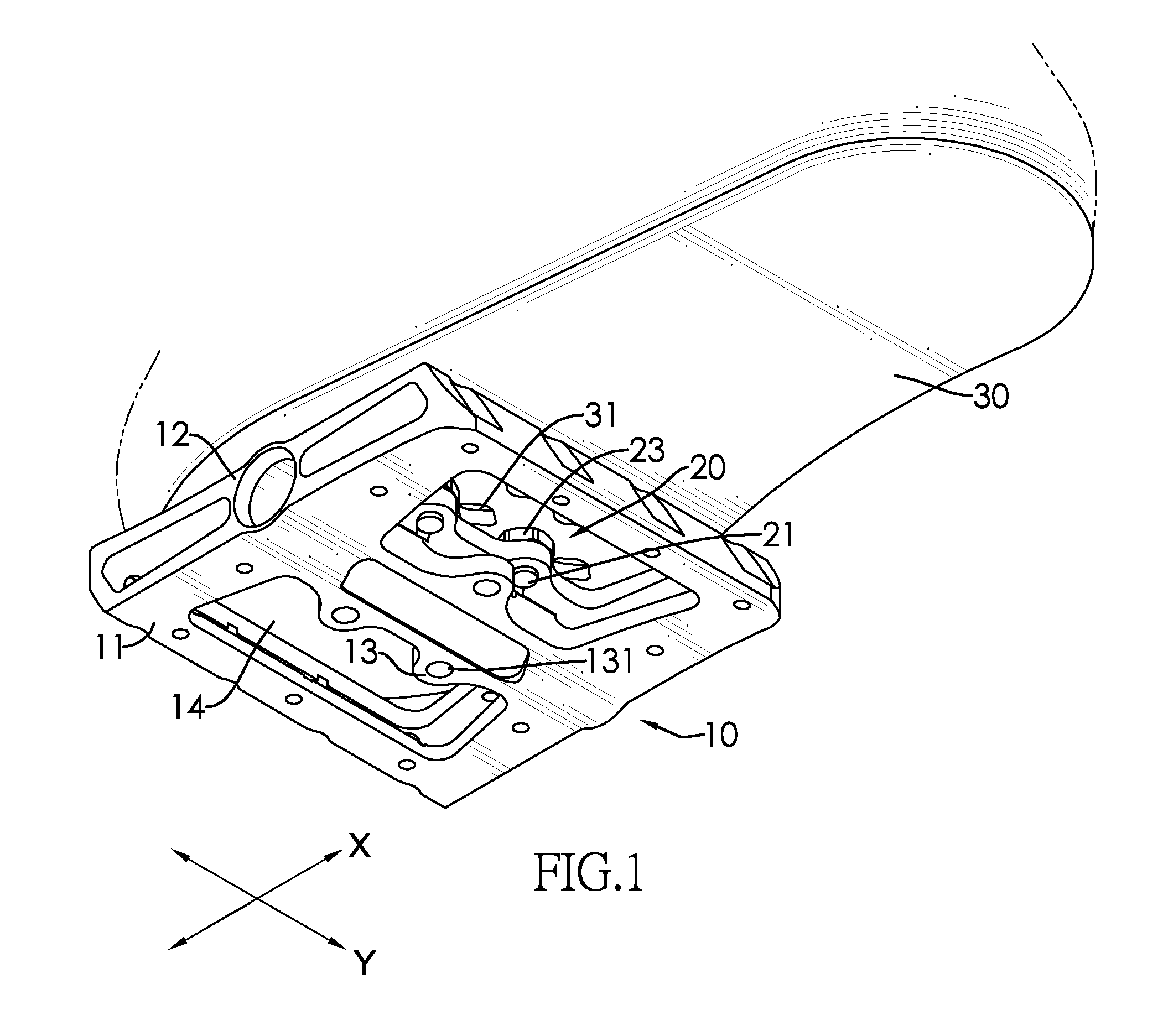
[0031]An X-axis direction is defined to extend from a center of a front wheel axle to a center of a rear wheel axle of a bicycle, and a Y-axis direction is defined to transversely and perpendicularly intersect with the X-axis direction. With reference to FIGS. 1, 2 and 5, a positioning device of a bicycle in accordance with the present invention has a pedal 10, multiple positioning elements 20 and a sole 30.

[0032]The pedal 10 has a body 11, a shaft tube 12 and multiple tabs 13. The body 11 has two openings 14 formed through the body 11. The shaft tube 12 is longitudinally and centrally formed through the body 11 along the Y-axis direction and is formed between the two openings 14. When the body 11 of the pedal 10 is positioned horizontally, the tabs 13 are formed on a periphery of the shaft tube 12 and respectively protrude forwards and backwards along the X-axis direction. Each tab 13 has a through hole 131 formed through the tab 13. The tabs 13 may be formed on a top and a bottom ...


PUM


Abstract

A shoe positioning device of a bicycle that has a pedal, a sole and multiple positioning elements. The pedal has multiple locating recesses formed therein. The sole is made of a resilient material. Each positioning element has a top end selectively engaging one of the locating recesses, thereby positioning a shoe and the pedal to increase cycling speed. Besides, easy disengagement of the shoe from the pedal reduces chances of accident in cycling.

Description

BACKGROUND OF THE INVENTION[0001]1. Field of the Invention[0002]The present invention relates to a positioning device, and more particularly to a shoe positioning device of a bicycle for conveniently snapping in and pulling out from a cyclist's sole.[0003]2. Description of the Related Art[0004]Aside from being a means for transportation and recreation, bicycles are also used for regular exercise, professional racing, and climbing. To win a bicycle racing or climbing game / tournament, increasing riding speed and efficiency of cyclists is the name of the game.[0005]With reference to FIG. 10, a shoe positioning device of a bicycle disclosed in Taiwanese utility model patent publication no. M317392 “Shoe Positioning Device of a Bicycle”, has a pedal 80 and a shoe locator 90. The pedal 80 has a recess 81, an opening 82, a shaft 83, a first engagement element 84 and a second engagement element 85. The recess 81 is recessed from one end of the pedal 80. The opening 82 is formed through the ...

Claims


Application Information

Patent Timeline
Patent Type & Authority Applications(United States)
IPC IPC(8): B62M3/08
CPCA43B5/14B62M3/086Y10T74/217
Inventor CHEN, CHUN-FENG
Owner HOPE IND
Learn More