
Battery cable clamp

a battery and clamping technology, applied in the direction of connection, cell component details, cell components, etc., can solve the problems of battery being cumbersome and difficult to release, not providing, and releasing the handles

Inactive Publication Date: 2008-04-01
MAC DONALD ANGUS BRYDEN
View PDF6 Cites 3 Cited by
  • Summary
  • Abstract
  • Description
  • Claims
  • Application Information

AI Technical Summary

Benefits of technology

Enables secure, safe, and tool-free connection and disconnection of battery booster cables to battery posts, preventing arcing and improving usability for both experts and non-experts by ensuring even force distribution across the battery post surface.

Problems solved by technology

However, release of the handles in such configurations of cable clamps to enable the jaws to close on the terminal of a battery can be cumbersome and difficult, and may not provide for a battery clamp which can which can be quickly engaged and disengaged from a battery post, or to engage and disengage the battery post without the need of any installation tooling.
In use, the serrated edge often does not allow an adequate amount of surface contact with the battery's electrical terminal.
This can cause arcing of the current in the vicinity of this connection possibly leading to ignition of the hydrogen gas evolved in the jumping or boosting process.
These drawbacks have prevented the widespread usage of booster cable by those not knowledgable in automotive technology or electrical circuitry.

Method used


Image

  • Battery cable clamp
  • Battery cable clamp
  • Battery cable clamp

Examples


Embodiment Construction

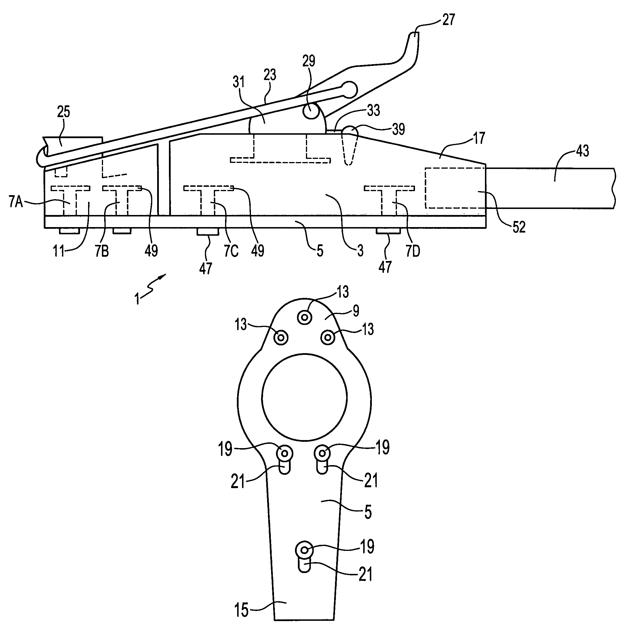
[0022]The battery cable clamp apparatus of the present invention, comprises a two part sectioned battery post contactor which is drawn together about a battery post in a sliding fashion along a lower attached base plate by an upper mounted buckle or latch mechanism.

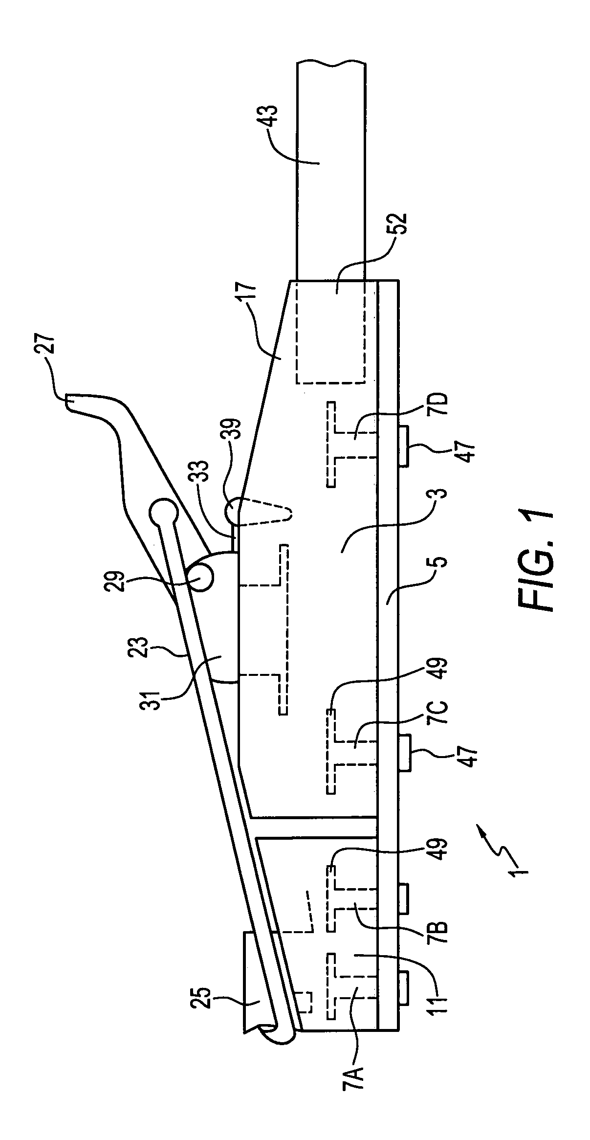
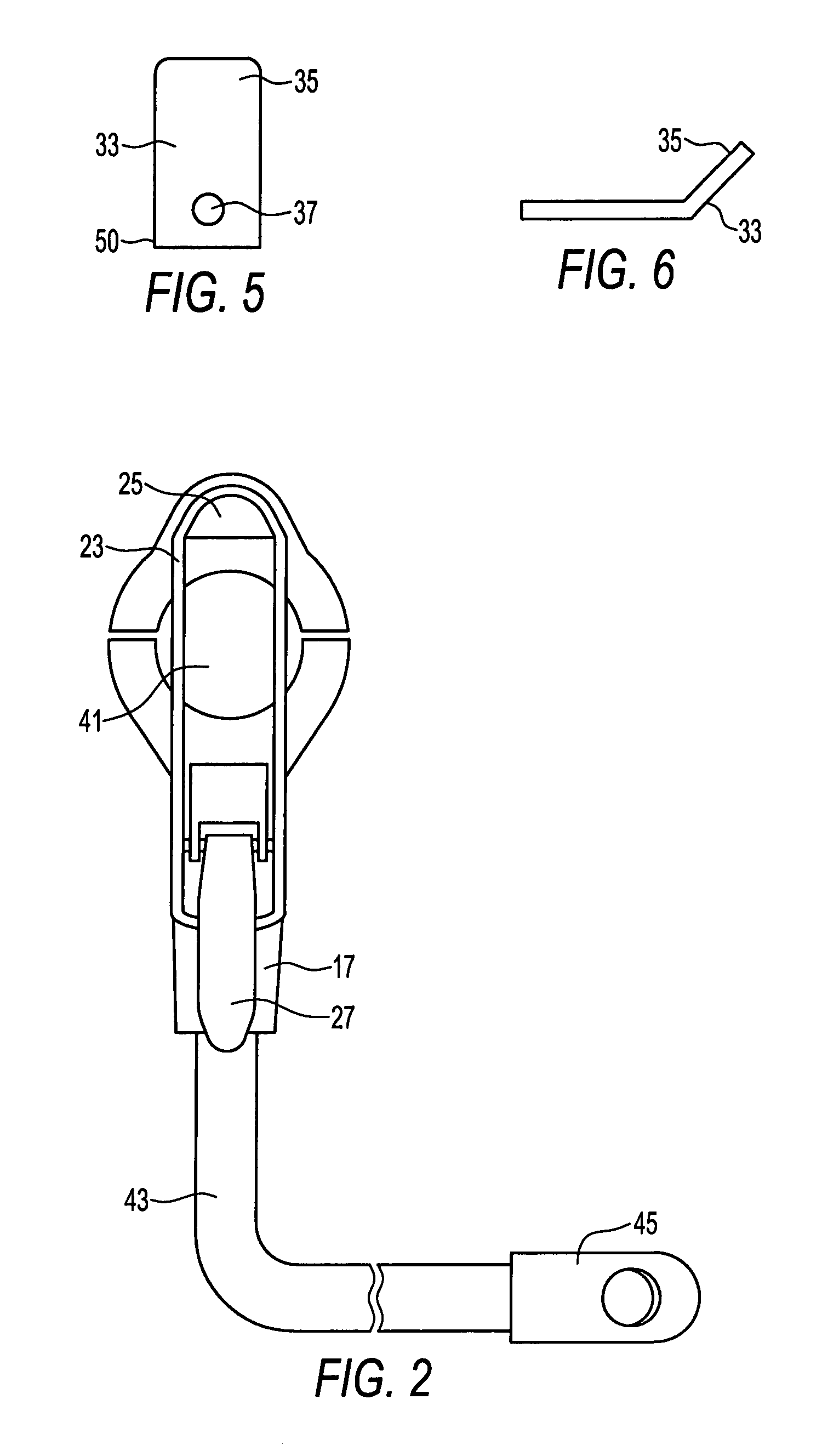
[0023]FIG. 1 illustrates a battery clamp 1 for use in connection therewith for removable securement to a battery post terminal (not shown). In a preferred embodiment, the battery clamp 1 comprises a main body portion 3, and a sliding plate 5 connected to the bottom of the main body portion 3, the sliding plate 5 being secured to the main body portion 3 with rivets (not shown) which can be imbedded into openings 7A–7D on the bottom of the main body portion 3. Preferably, the main body portion 3 is constructed from lead, and the sliding plate is constructed of steel, though it is also conceivable that other materials could be used, as would be apparent to a person skilled in the art.

[0024]FIG. 3 illustrates a bottom view of...


PUM

PropertyMeasurementUnit
diameteraaaaaaaaaa
areaaaaaaaaaaa
tension forceaaaaaaaaaa

Abstract

This invention is an improved battery booster cable and clamp apparatus that operates in conjunction with a two piece split electrically conductive housing that is adapted to allow a battery terminal to reside therein, the two pieces of the housing being slid into or away from gripping contact with the terminal along a connecting base plate by utilizing a spring energized buckle or clamp assembly.

Description

BACKGROUND OF THE INVENTION[0001]The present invention relates generally to a battery booster cable, and more particularly, to a clamp assembly that is used in connection therewith for removable securement to a battery post terminal, which does not require the use of any installation tools, and which provides greater ease in attachment / detachment from a conventional battery terminal post.[0002]Battery “booster” or “jumper” cables are well known in the art for electrically interconnecting a discharged battery of a stalled vehicle in parallel with an external source of electrical energy, typically the charged battery of another vehicle. This is done to draw sufficient current from the charged battery to temporarily increase the capacity of the discharged battery, thereby allowing the stalled vehicle to be started. Typically, a pair of electrically conductive cables are joined together in side-by-side relationship to form a single booster cable which is easy to transport. Each cable ha...

Claims


Application Information

Patent Timeline
Patent Type & Authority Patents(United States)
IPC IPC(8): H01R4/48H01M50/543H01R11/28
CPCH01M2/1005H01R11/282H01R11/281H01M2/305Y02E60/10H01M50/256H01M50/543
Inventor MAC DONALD, ANGUS BRYDEN
Owner MAC DONALD ANGUS BRYDEN
Learn More