Novel Design For Mounting Assembly For Photovoltaic Arrays

a photovoltaic array and mounting assembly technology, applied in the direction of heat collector mounting/support, light and heating apparatus, furniture parts, etc., can solve the problems of long and arduous installation significant amount of time spent leveling the mounting assembly, and many drawbacks of conventional mounting assemblies, etc., to achieve rapid assembly and rapid height adjustment

Inactive Publication Date: 2011-03-03
BAP POWER PTE
View PDF10 Cites 7 Cited by
  • Summary
  • Abstract
  • Description
  • Claims
  • Application Information

AI Technical Summary

Benefits of technology

[0009]In view of the foregoing, this invention provides novel systems and methods for implementing improved designs of mounting assemblies which allow for rapid assembly and rapid adjustment of height.

Problems solved by technology

Unfortunately, the conventional mounting assembly suffers from several drawbacks.
By way of example, installing conventional mounting assemblies is a long and arduous task.
A significant amount of time is spent leveling the mounting assembly.
As another example, it is difficult to adjust a height of the conventional mounting assembly.
Regardless of how a height adjustment is accomplished, it is clear that the above-mentioned drawbacks associated with leveling compound the process of height adjustment in a conventional design.
As yet another example, even after enduring such cumbersome efforts, often times the resulting mounting assembly does not have the requisite flatness or is not level.
Consequently, subsequent photovoltaic panels installed on conventional mounting assemblies are frequently crooked and / or are bent.
Such crooked and bent panels are undesirable as they reduce the efficiency of the panel.
As yet another example, the conventional design with all the different interconnecting components involved, represents a complicated design that is expensive to implement.

Method used


Image

  • Novel Design For Mounting Assembly For Photovoltaic Arrays
  • Novel Design For Mounting Assembly For Photovoltaic Arrays
  • Novel Design For Mounting Assembly For Photovoltaic Arrays

Examples


Embodiment Construction

[0027]In the following description numerous specific details are set forth in order to provide a thorough understanding of the present invention. It will be apparent, however, to one skilled in the art that the present invention may be practiced without limitation to some or all of these specific details. In other instances, well known process steps have not been described in detail in order to not unnecessarily obscure the invention.

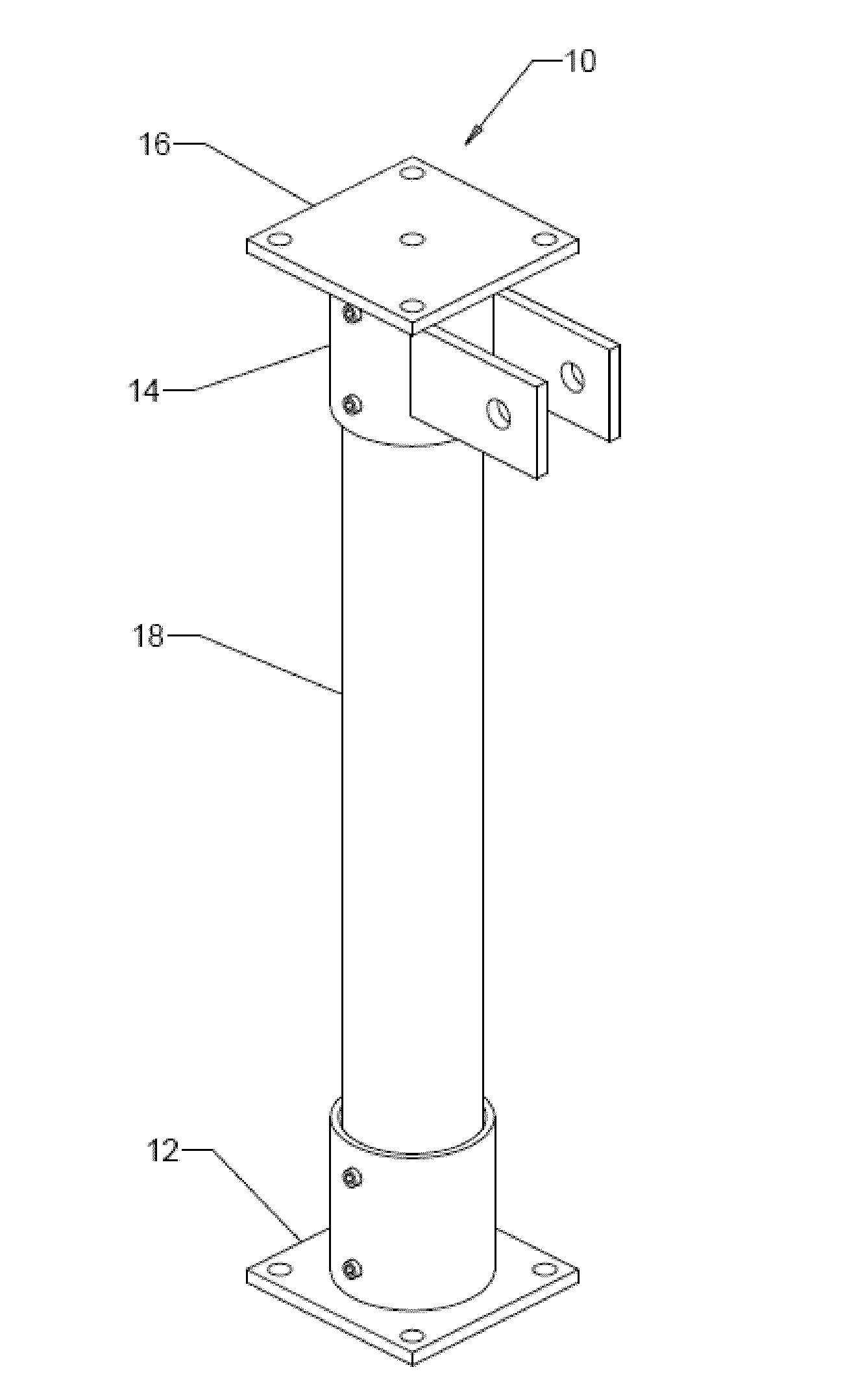
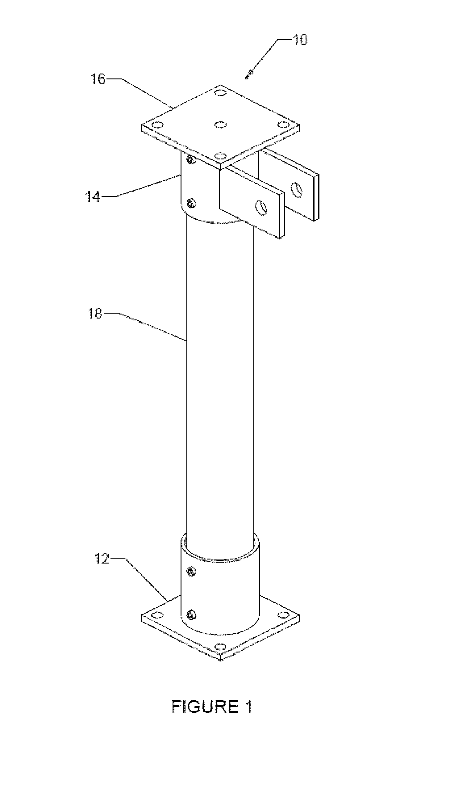
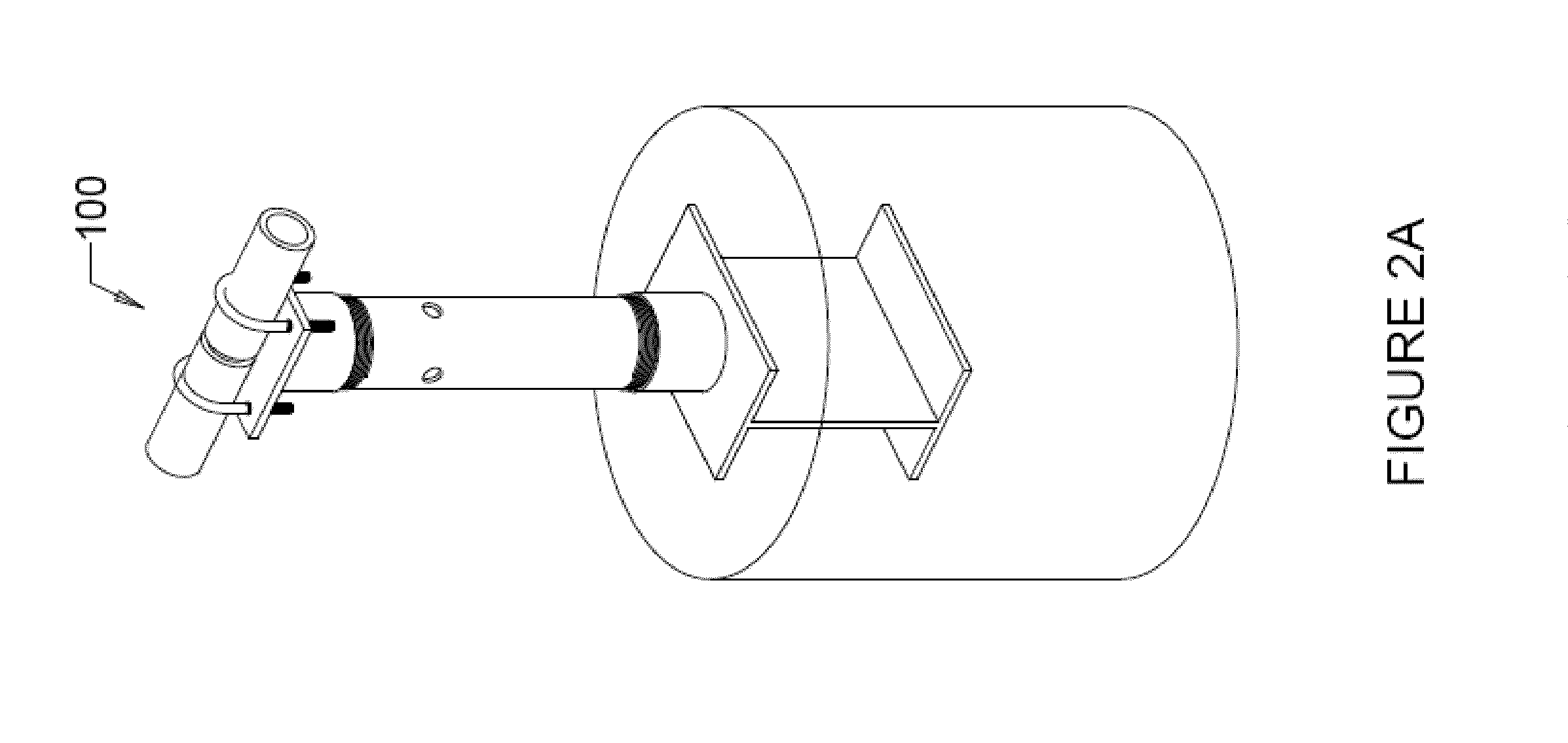
[0028]FIG. 2A shows a perspective view of a mounting assembly, according to one embodiment of the present invention, used for installation of photovoltaic panels. Details of the various components involved in the manufacture of assembly 100 are shown in greater detail in FIG. 2B discussed below.

[0029]FIG. 2B shows an exploded front view of mounting assembly 100. Mounting assembly 100 includes a pipe 108 disposed between a top component 104 and a base component 102. Pipe 108, top component 104, a base component 102 may be, but are not necessarily, made f...


PUM

PropertyMeasurementUnit
diameteraaaaaaaaaa
diameteraaaaaaaaaa
depthaaaaaaaaaa

Abstract

A mounting assembly is described. The mounting assembly includes: (a) a pipe having a first threaded end and a second threaded end; (b) a base component having a base portion and a threaded connecting portion; (c) a top component having a top portion and a threaded portion, the top component being capable of supporting a photovoltaic panel thereon; and (d) wherein the first threaded end of the pipe and the threaded connecting portion of the base component include threads such that the first threaded end rotatably engages in a first direction with the threaded connecting portion, and the second threaded end of the pipe and the threaded portion of the top component include threads such that the first threaded end rotatably engages in a second direction with the threaded portion of the top component, the first direction is opposite to the second direction, and the first threaded end and the second threaded end are substantially cylindrical.

Description

BACKGROUND OF THE INVENTION[0001]The present invention relates generally to mounting assemblies used for installation of photovoltaic arrays. More particularly, the present invention relates to improved designs of mounting assemblies which allow for their rapid assembly and rapid height adjustment.[0002]FIG. 1 shows a conventional mounting assembly 10 used for installation of photovoltaic panels. Assembly 10 includes a base component 12 and a top component 14. Top component 14 has disposed at one end a supporting plate 16, and at another end a tube portion 18. During the assembly of a photovoltaic panel, the appropriate frame and railing are built on supporting plate 16. A photovoltaic panel (not shown to simplify illustration) is ultimately secured on the railing.[0003]Tube portion 18 at one end connects to supporting plate 16 using set screws. At the other end, tube portion 18 connects to base component 12. Specifically, base component 12 has a cavity which is large enough to rece...

Claims


Application Information

Patent Timeline
Patent Type & Authority Applications(United States)
IPC IPC(8): F16M13/00B23P11/00
CPCY02E10/50F24J2/5232Y10T29/49826Y02E10/47H02S20/00F24J2/525F24S25/65F24S25/12F24S25/617F24S2025/802
Inventor PHAM, WILLIAMGOLDIN, ANDREW B.PARSLOW, MARK A.
Owner BAP POWER PTE
Why Eureka
Try Eureka