Cycle propelling mechanism

Inactive Publication Date: 2011-03-03
HUNG TA CHUN
View PDF17 Cites 15 Cited by
  • Summary
  • Abstract
  • Description
  • Claims
  • Application Information

AI Technical Summary

Benefits of technology

[0016]The primary objective of the present invention is to provide a cycle propelling mechanism including a simplified structure for allowing the cycles to be easily and effectively o

Problems solved by technology

However, the foot pedals are rotated or driven cyclically by the user, and only about one quarter of the cyclically moving stroke of the foot pedals may be effectively operated or driven or propelled by the user such that the user may not effectively operate or drive or propel the foot pedals.
However, the foot pedals and the pedal levers may only be stepped up and down by the user, and the user may not effectively exercise his muscle groups.
In addition, the pedal levers have an increased horizontal stroke which is perpendicular to the active force and which is useless and which may not do work and which includes a decreased efficiency, such that the typical cycle propelling mechanisms may not be merchandized.
However, the complicated coupling mechanism may not be easily manufactured and assembled and may greatly increase the manufacturing cost for the typical bicycle propulsion and speed change means.
In addition, the s

Method used


Image

  • Cycle propelling mechanism
  • Cycle propelling mechanism
  • Cycle propelling mechanism

Examples


Example

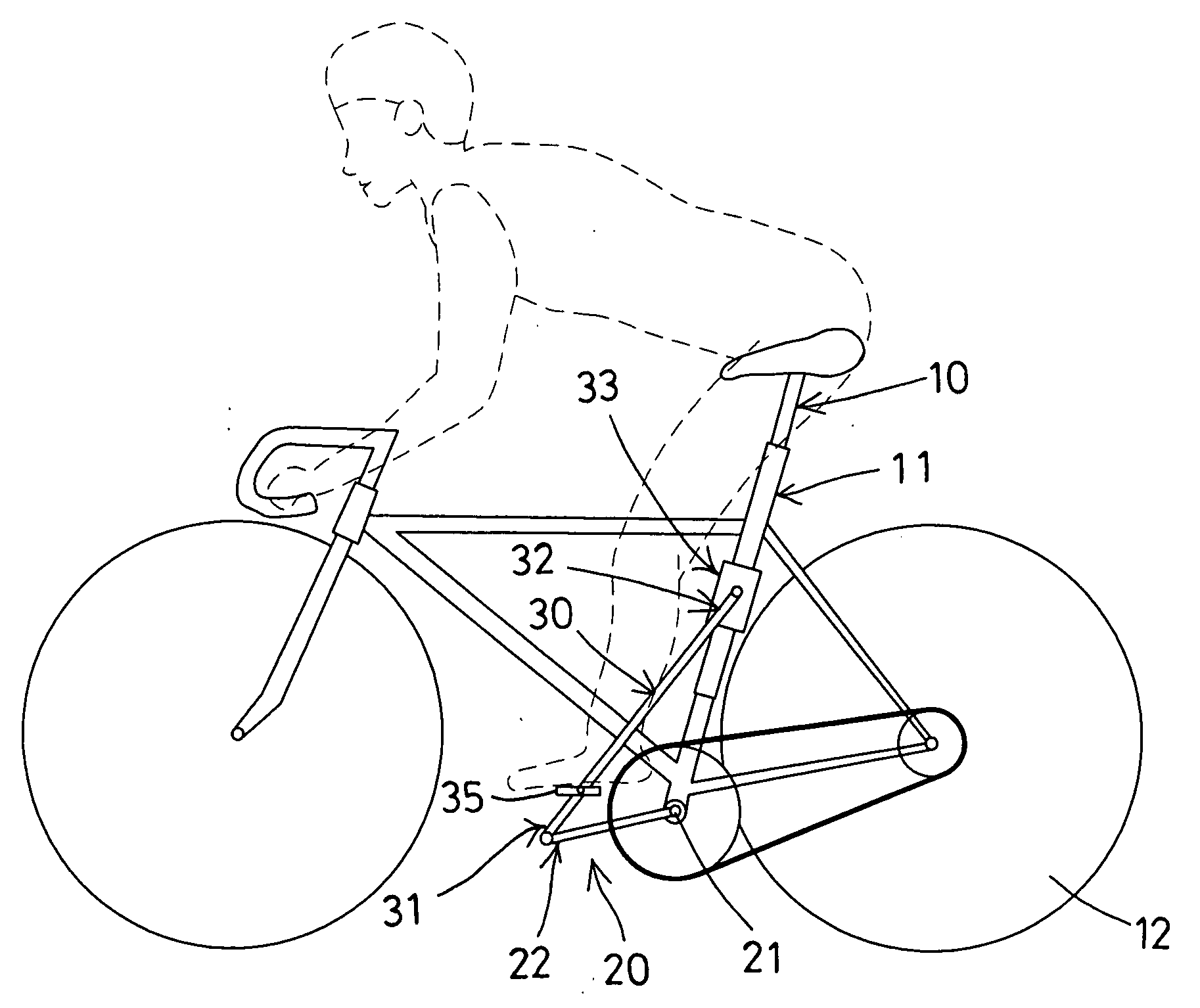
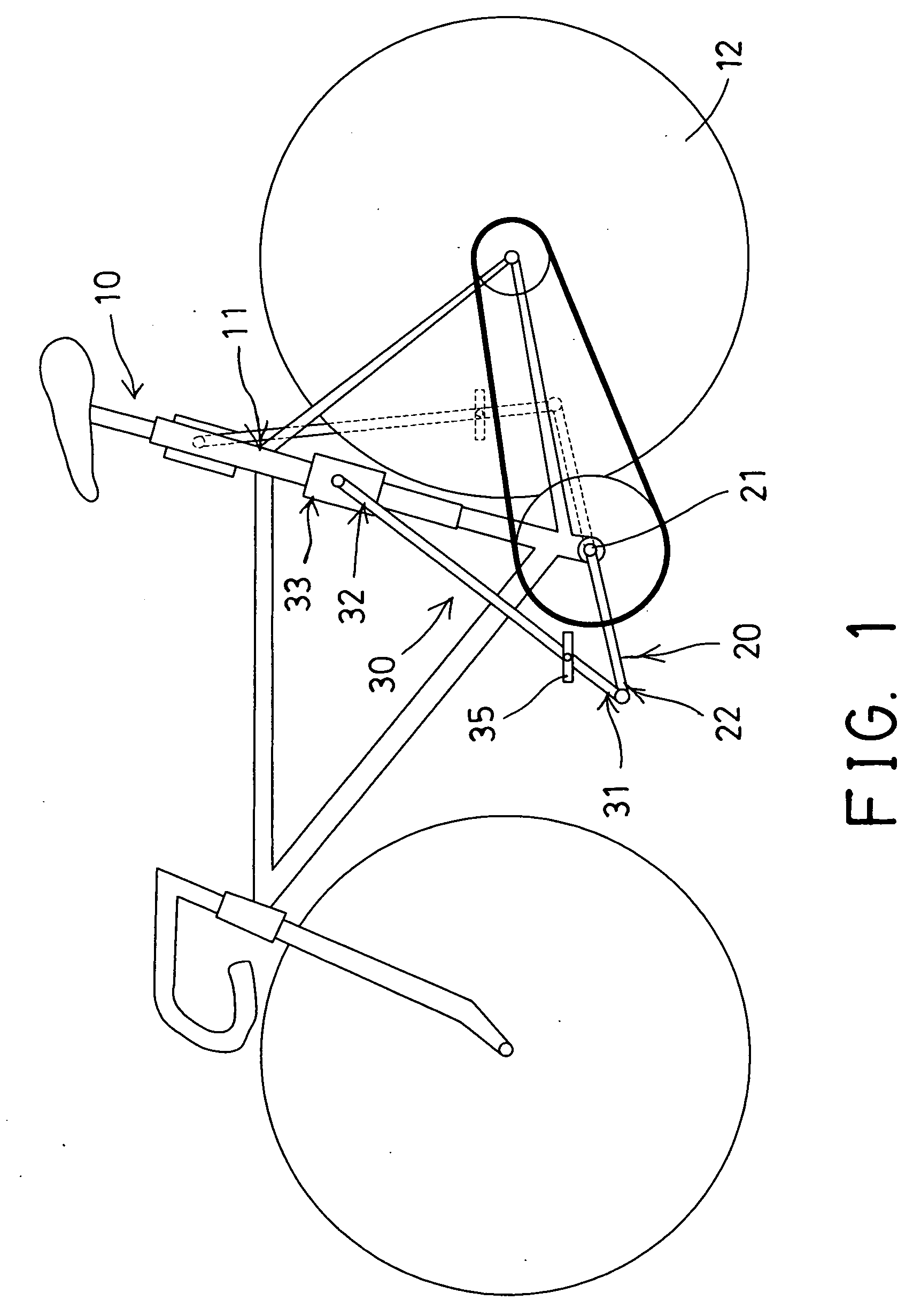
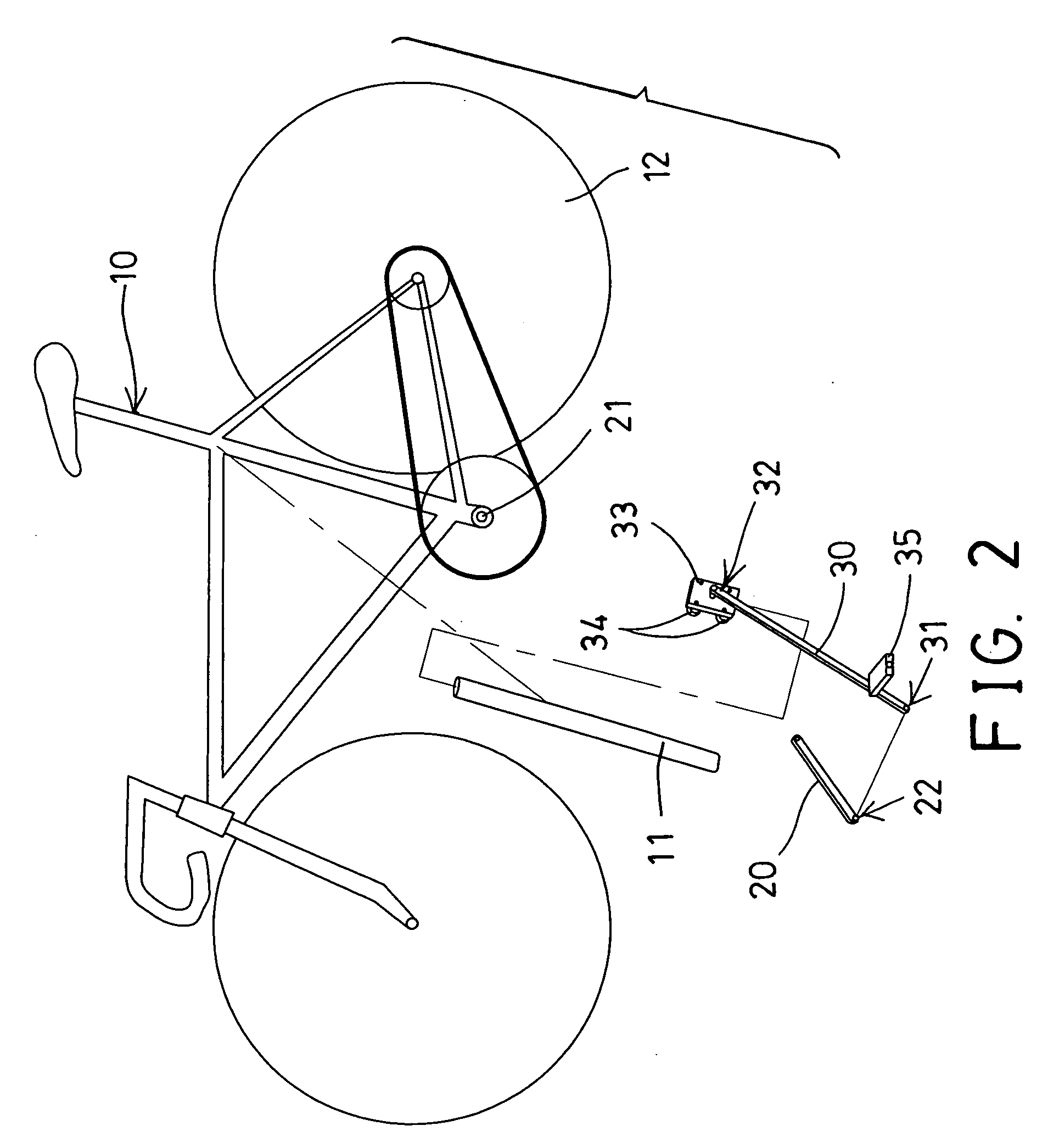
[0027]Referring to the drawings, and initially to FIGS. 1 and 2, a cycle propelling mechanism in accordance with the present invention comprises a cycle frame 10 including a track or rail 11 attached or mounted or provided or secured onto the cycle frame 10 and arranged up and down relative to the cycle frame 10 and disposed or arranged slightly inclined relative to the cycle frame 10, one or more (such as two) wheels 12 are attached or mounted or secured onto the cycle frame 10 for forming a unicycle, a bicycle, a tricycle or the like, and one or more (such as two) cranks 20 are pivotally or rotatably coupled to the cycle frame 10 with a main drive shaft 21 or coupled to the main drive shaft 21 of the cycle frame 10 for allowing the cranks 20 to be rotated or driven cyclically relative to the cycle frame 10.

[0028]One or more (such as two) links or levers 30 each include one end or lower end 31 pivotally or rotatably coupled to the respective free end 22 of the crank 20, and another...


PUM


Abstract

A cycle propelling mechanism includes a rail disposed on a cycle frame, two cranks rotatably coupled to the cycle frame with a main drive shaft, two levers each include one end pivotally coupled to the crank and the other end slidably coupled to the rail for allowing the levers to be moved cyclically relative to the cycle frame, and two foot pedals pivotally attached to the levers for being stepped and operated by user's feet and for allowing the cranks and the lever to be rotated relative to the cycle frame in an elliptical moving stroke and for allowing the foot pedals to be stepped and moved for a longer stepping or moving stroke by the user, and for effectively exercising the more or bigger muscle groups of the user, and for applying bigger power to the cycle propelling mechanism.

Description

BACKGROUND OF THE INVENTION[0001]1. Field of the Invention[0002]The present invention relates to a cycle propelling mechanism, and more particularly to a cycle propelling mechanism including a simplified structure for allowing the cycles to be easily and effectively operated or driven or propelled by the user and for effectively exercising the more or bigger muscle groups of the user, and for applying bigger power to the cycle propelling mechanism.[0003]2. Description of the Prior Art[0004]Typical cycle propelling mechanisms comprise a pair of foot pedals rotatably coupled to a main drive shaft or a cycle device, such as a unicycle, bicycle, tricycle or the like with cranks for allowing the main drive shaft and the wheels of the cycle device to be rotated or driven by the foot pedals.[0005]However, the foot pedals are rotated or driven cyclically by the user, and only about one quarter of the cyclically moving stroke of the foot pedals may be effectively operated or driven or propel...

Claims


Application Information

Patent Timeline
IPC IPC(8): B62M1/04B62M1/24
CPCB62M1/24B62M1/26
Inventor HUNG, TA CHUN
Owner HUNG TA CHUN
Why Eureka
Try Eureka