A device and a method for downhole energy generation

Active Publication Date: 2011-03-03
TENDEKA
View PDF21 Cites 46 Cited by
  • Summary
  • Abstract
  • Description
  • Claims
  • Application Information

AI Technical Summary

Benefits of technology

[0045]In a preferred embodiment the pressure compensated area of the device is gas filled, and the interface between the vibrating assembly and the pressure compensated area of the device is a metal process bellows. By means, a gas filled environment would impose far less damping on an oscillating magnet/coil assembly than a liquid filled environment. Further, a flexible metal bellows interface would also provide for a mechanically very flexible connection between the well regime where the vibrating assembly is located and the pressure compensated, gas filled compartment where the energy harvester is

Problems solved by technology

New well designs such as the ones described above have in a number of cases entailed a new challenge in the form of inaccessible areas of the well.
It is normally deemed as non-desirable to perform interventions in the side branches of a well as the risk of getting stuck in the junction between branches and/or causing other types of damage to the well are perceived to be of too high a risk.
As a consequence, measurement and control tasks in branch wells are normally limited to areas where the branch enters the main bore of the well, and can normally not be executed within the branch(es) itself.
Here, interventions such as data acquisition or barrier installation jobs are scarce due to low availability and high costs associated with required drilling rigs or intervention vessels that need to be mobilised for the work.
In addition to the problem with non-accessible wells and/or areas in wells, several other factors may inflict challenges to the operation of well equipment.
Such factors include debris/fill material, corrosion, scaling (salt deposits), and damage to control lines and line connectors.
As an example, debris such as sand, scale (salt deposit) particles or steel fragments from drilling or perforation operations may deposit on top of intervention plugs, making it very difficult to retrieve them after usage.
Scale and corrosion on a plug itself may cause similar problems.
A limitation with autonomous and/or wireless based downhole application is the provision of power for system operation; as all autonomous devices are dependant on local supply of power to be operated in a proper manner.
However, such batteries entail several challenges which limit the possible use of wireless telemetry and autonomous devices:Non-rechargeable batteries suffer from a phenomenon referred to as “self-discharge”.
Hence, due to the subject of self-discharge, it is a challenge to make optimum usage of the energy potential that non-rechargeable batteries represent.Non-rechargeable batteries will in many cases provide insufficient amounts of energy required for multiple and/or high power requiring operations of a downhole device such as a valve.
This entails that an autonomous system powered by a non-recha

Method used


Image

  • A device and a method for downhole energy generation
  • A device and a method for downhole energy generation
  • A device and a method for downhole energy generation

Examples


Example

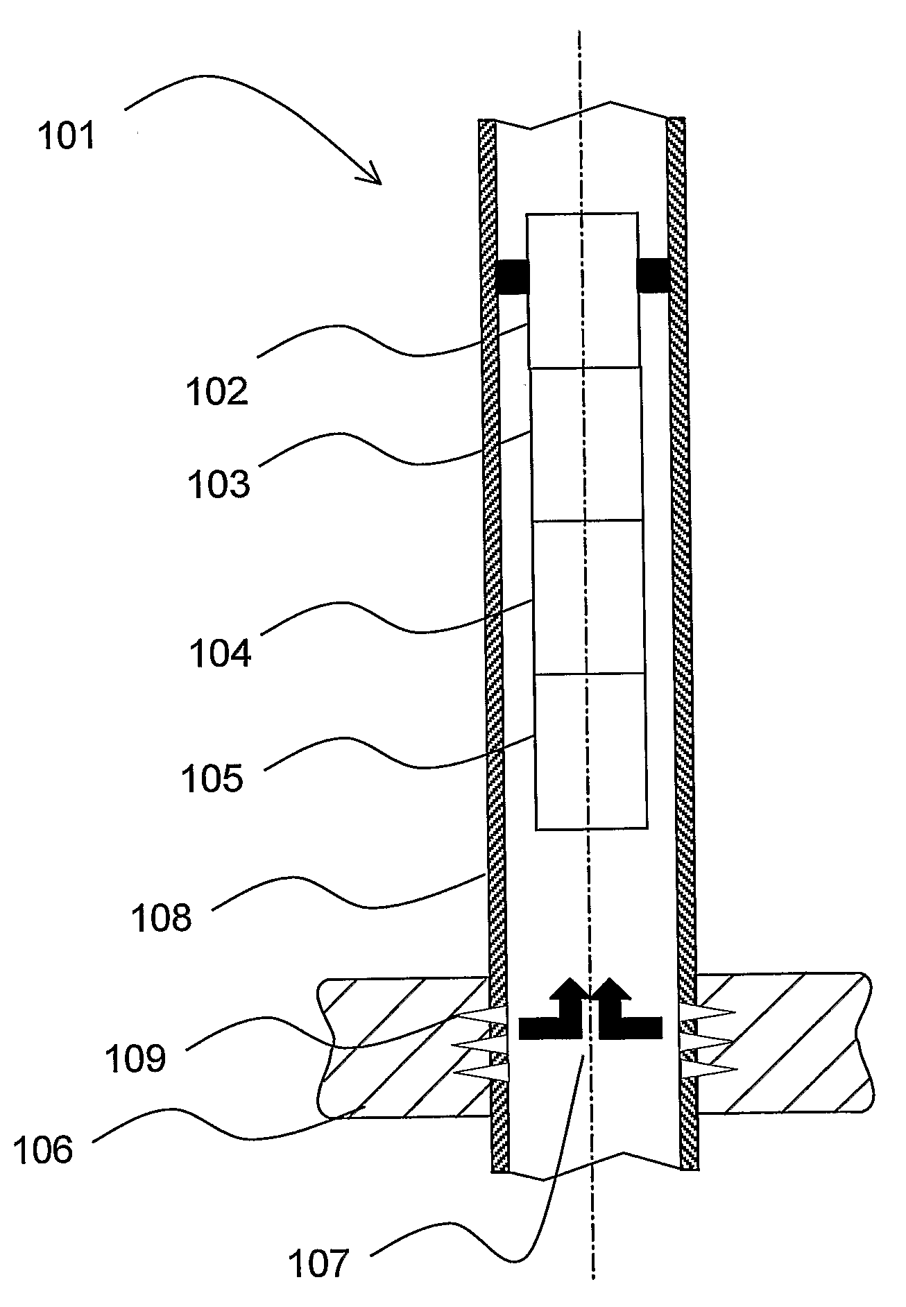
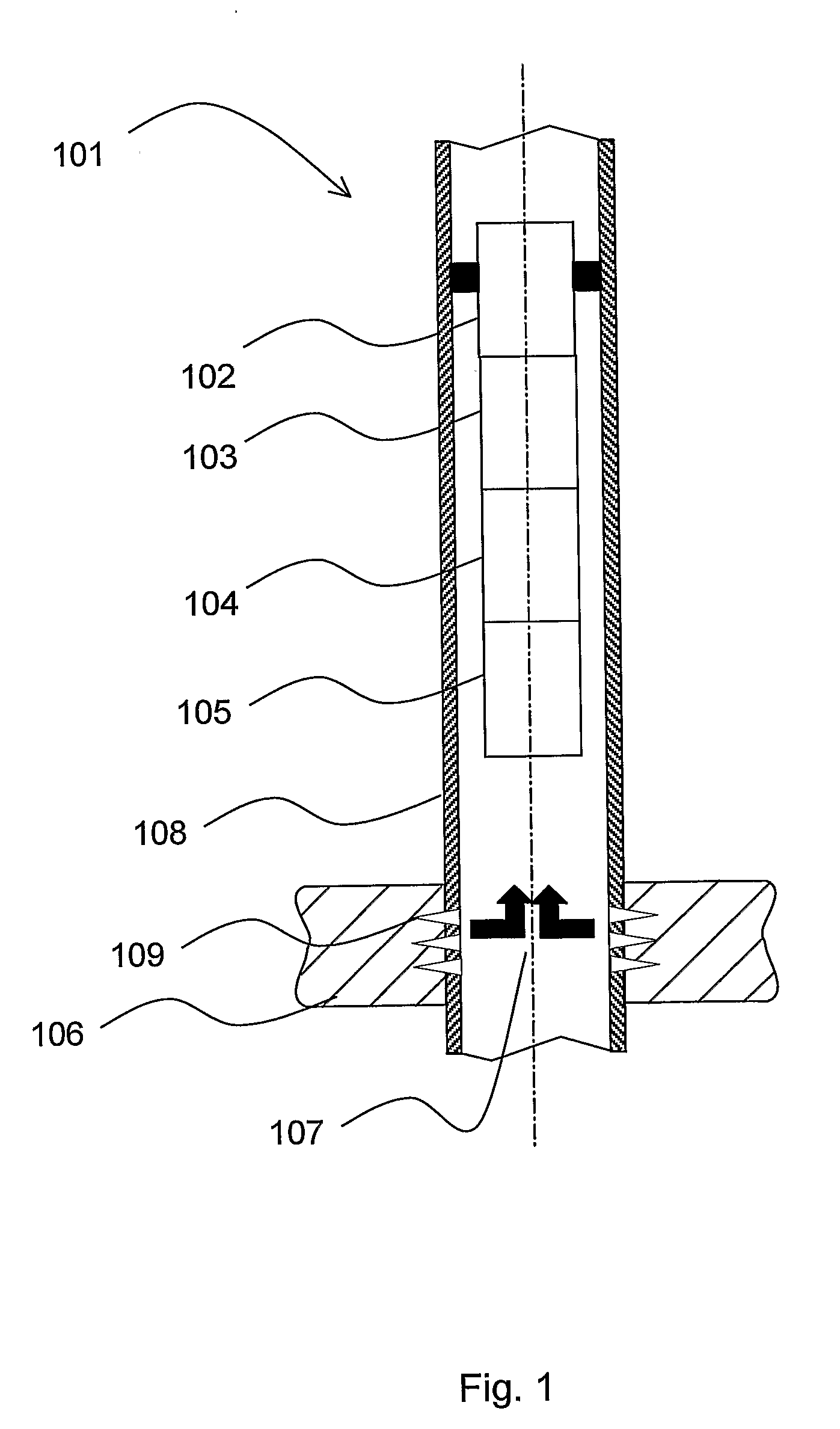
[0075]FIG. 1 illustrates an example of a subterranean well 101 which embodies principles of the present invention. It is to be understood that the various embodiments of the present invention described herein may be utilized in various orientations, such as inclined, inverted, horizontal, vertical, etc., and in various configurations, without departing from the principles of the present invention.

[0076]The well 101 is described herein as being a producing well in which fluid is produced from a reservoir formation 106 into a tubular string 108, and is then flowed through this tubular string 108 to surface. However, it is to be clearly understood that the principles of the present invention may be incorporated into other types of wells and other systems, for example, where fluid is injected into a formation or circulated in the well (such as drilling operations), where fluids pass from a relatively high pressure source to a relatively low pressure source within the well, or where flui...


PUM


Abstract

The present disclosure relates to a downhole electrical energy generating device (105) and a method for transforming energy from a fluid flow (107) passing the device (105), including: at least one vibrating assembly (250) influenced by the fluid flow (107) to oscillate, the vibrating assembly (250) including an elongated body (206) having a longitudinal axis being arranged non-parallel with the fluid flow (107), a stiff body (205) connecting the elongated body (206) to a portion of the device located downstream of said elongated body (206); at least one energy harvester (203) influenced by the vibrating assembly (250), wherein the energy generating device (105) is provided with means (204) for influencing the oscillation frequency of the vibrating assembly (250).

Description

[0001]This invention regards a system and a method related to local energy generation for downhole tools and devices used in association with wells for the production of hydrocarbons.BACKGROUND[0002]Wells for the production of hydrocarbons are designed in a range of different ways, depending on many influencing factors. Such factors include production characteristics, safety, well servicing, installation- and re-completion issues, downhole monitoring and control requirements and compartmentalisation of producing zones.[0003]Further, as wells mature, they are normally serviced using techniques known as per se on regular intervals.[0004]Intervention services such as wireline and coil tubing are most commonly applied. The service could, as an example, be conducted for data acquisition purposes, for zone isolation or opening for production from new zones, for zone stimulation, for removal of salt deposits or to fix leakages in the wells tubular.[0005]Common well components such as plugs...

Claims


Application Information

Patent Timeline
IPC IPC(8): F03B13/10
CPCE21B41/0085
Inventor TINNEN, BARD MARTINSORTVEIT, HAVAR
Owner TENDEKA
Why Eureka
Try Eureka