Positioning apparatus for dental x-ray procedures

a technology for positioning apparatus and dental x-ray, which is applied in the field of positioning apparatus for dental x-ray procedures, can solve the problems of time-consuming changes between sensors, sensor holders and bite blocks

Active Publication Date: 2011-03-03
DENTSPLY SIRONA INC
View PDF5 Cites 13 Cited by
  • Summary
  • Abstract
  • Description
  • Claims
  • Application Information

AI Technical Summary

Problems solved by technology

At best, it is time consuming to change between sensors, sensor holders and bite blocks.

Method used


Image

  • Positioning apparatus for dental x-ray procedures
  • Positioning apparatus for dental x-ray procedures
  • Positioning apparatus for dental x-ray procedures

Examples


Embodiment Construction

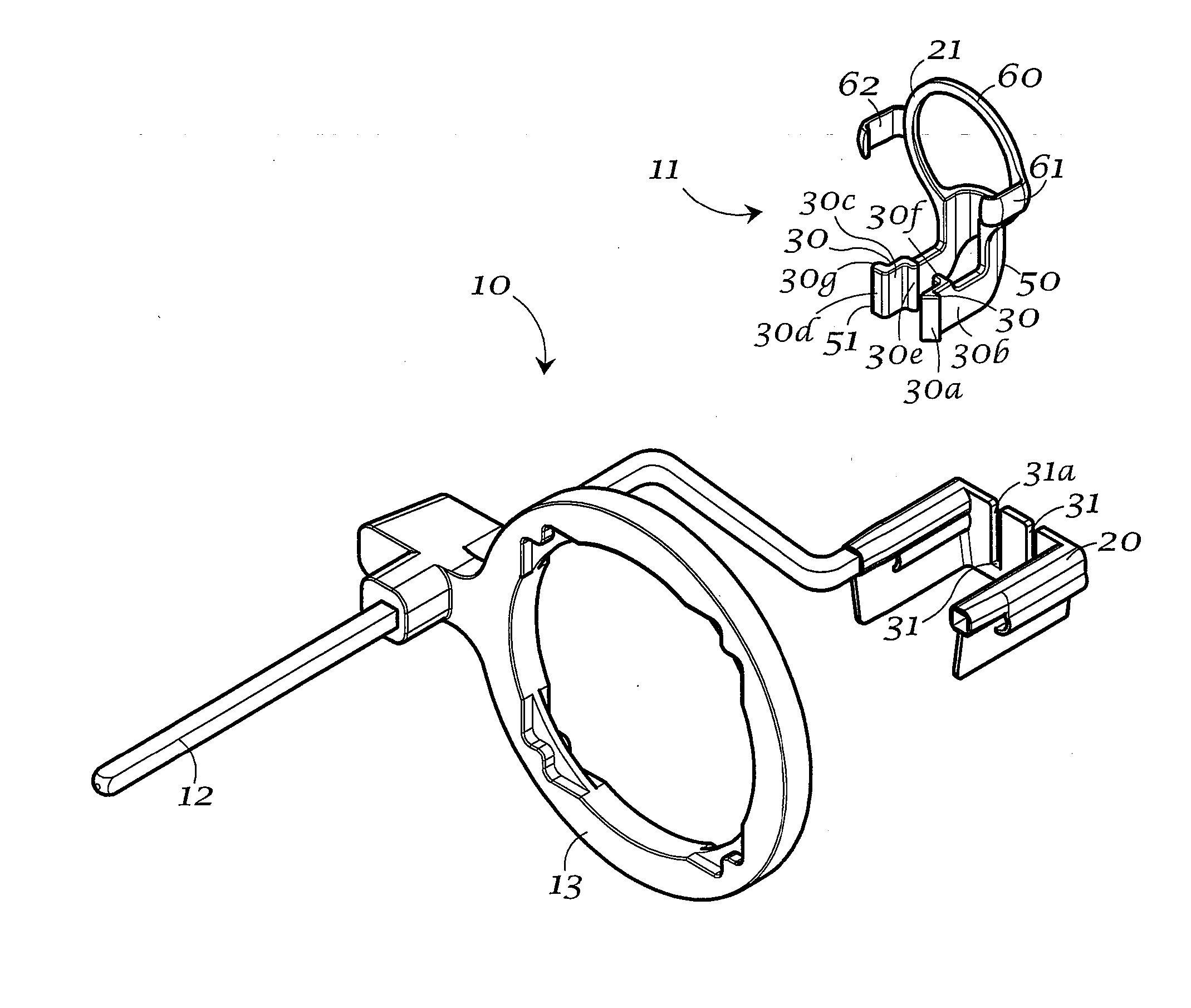
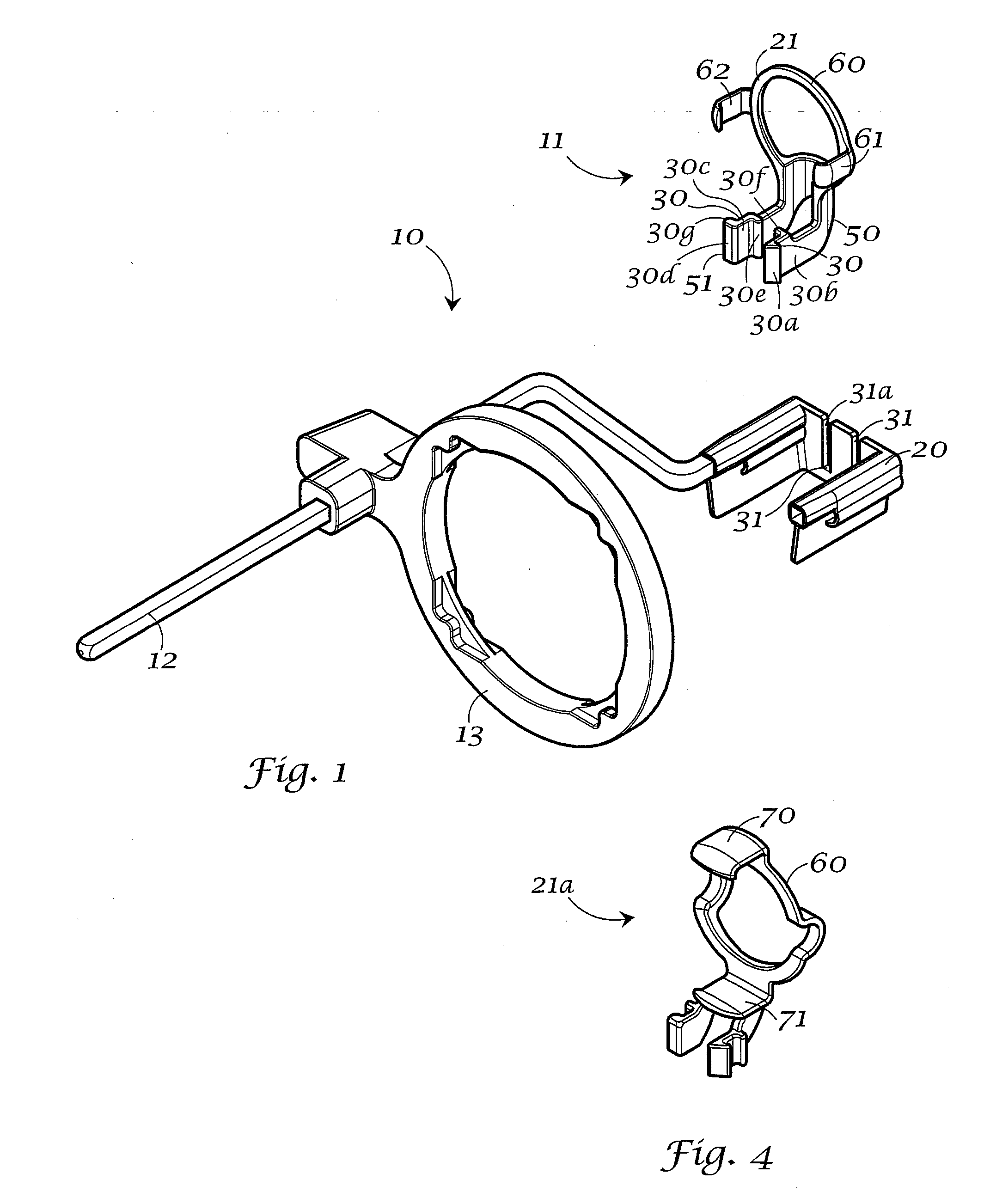
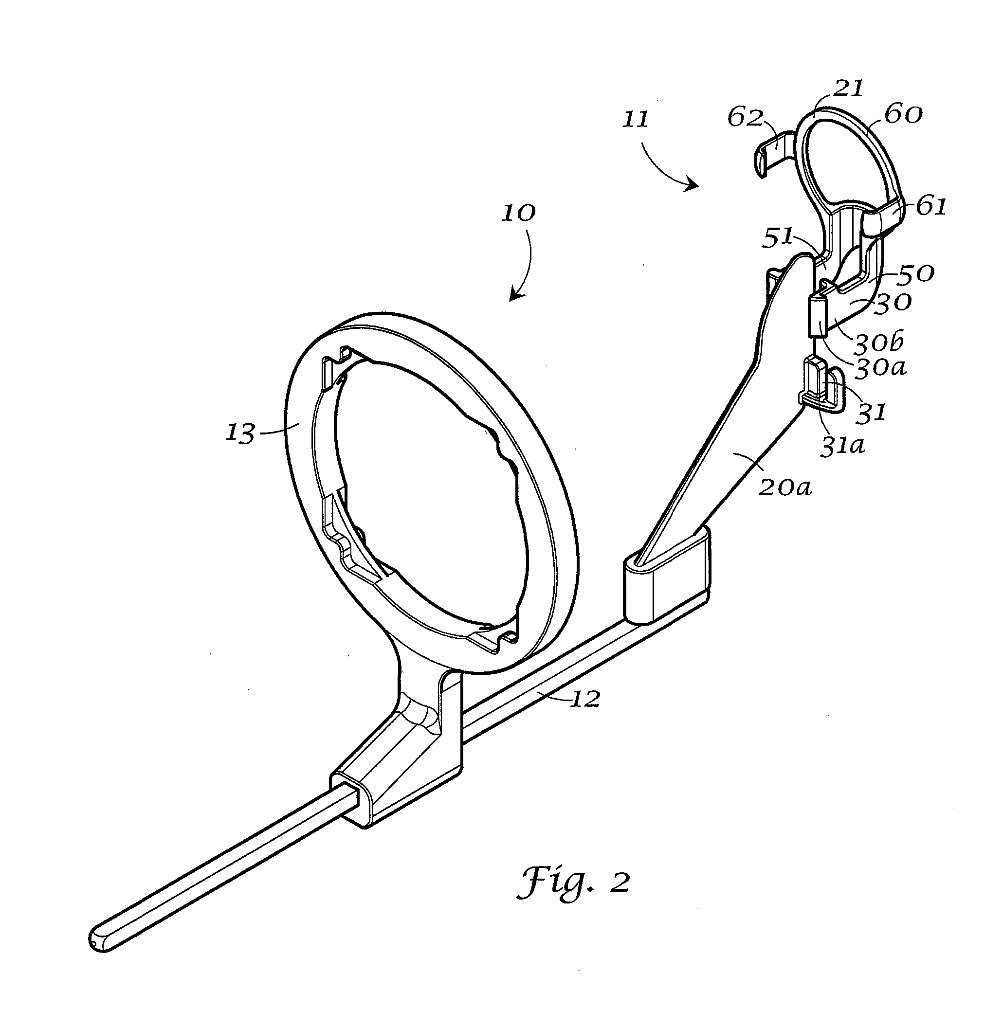
[0030]An x-ray sensor-positioning device according to the invention is generally designated by the number 10 on the attached drawings. Assembly 10 is preferably configured to have a conventional dental x-ray support or guide arm 12. An exemplary guide arm and its use with a bite block for taking a dental x-ray is shown in U.S. Pat. No. 3,473,026, which is incorporated by reference for its disclosure of a guide arm and bite block. As shown in FIGS. 1-3, guide arm 12 may be configured to be affixable to an x-ray tube collimator-positioning ring 13 in a conventional manner. Such a ring is also shown for example, in U.S. Pat. No. 3,473,026 and, U.S. Des. 237,016 which are incorporated by reference for disclosure of such a ring.

[0031]Aiming ring 13a, FIG. 5, shows a plurality of regularly spaced, opposing steps 13b for receiving and registering a collimator (not shown). One set of such steps is known in the art (see for example, U.S. Des. 237,016). One embodiment of the present invention...


PUM


Abstract

A dental bite block (20) and sensor holder (21) assembly (11) has a bite block (20) configured (31) to detachably affix to a sensor holder (21). Affixing surfaces (30, 31) are provided between the bite block (20) and the sensor holder (21) such that the sensor holder (21) is removably affixed to the bite block (20). An alternative guide arm (100) has more than one attachment site (101a, 101b) for removably affixing a sensor holder (102, 103, 104) to the guide arm (100).

Description

TECHNICAL FIELD[0001]The present invention is a sensor holder apparatus having a bite block and aiming ring mounted to a guide arm, for use during dental x-ray procedures. More particularly, the invention is a modular bite block and sensor holder assembly having a sensor support or guide arm, such that a given sensor can be used with bite blocks for different x-ray procedures. Also, provided is an improved aiming ring for use in dental x-ray procedures. Sensor holders of various designs can be removably affixed to more than one location on the support arm, facilitating a plurality of dental x-ray procedures.BACKGROUND OF THE INVENTION[0002]Dental radiographs are made using x-ray examination units, often including an x-ray cone or tube positioned proximate the patient and aligned to take x-rays of certain teeth. Dental x-ray sensors, including films, charge coupled devices, phosphor imaging plates or the like, often have a generally flat or plate-like configuration and standardized d...

Claims


Application Information

Patent Timeline
Patent Type & Authority Applications(United States)
IPC IPC(8): G21K1/02A61B6/14
CPCA61B6/145A61B6/4435A61B6/587
Inventor STEWARD, JR., CURTIS L.
Owner DENTSPLY SIRONA INC
Why Eureka
Try Eureka