
Integrated tissue processing and embedding systems, and methods thereof

a tissue processing and tissue technology, applied in the field of integrated tissue processing and embedding systems, can solve the problems of affecting examination or analysis, and affecting the examination effect of the tissue,

Active Publication Date: 2011-03-03
SAKURA FINETEK U S A
View PDF8 Cites 12 Cited by
  • Summary
  • Abstract
  • Description
  • Claims
  • Application Information

AI Technical Summary

Benefits of technology

The patent text describes a system and method for processing tissue in a histological laboratory. The system includes an automated tissue processor and an automated embedding system, which are separate and unconnected instruments. The tissue needs to be manually removed from the automated tissue processor and moved to the automated embedding system before embedding can begin. This can be time-consuming for laboratory personnel and may lead to instrument downtime and reduced productivity. The invention aims to solve this problem by integrating the automated tissue processor and the automated embedding system, allowing for a more efficient and automated tissue processing and embedding process.

Problems solved by technology

Cutting a tissue that has not undergone tissue processing may tend to be challenging.
Force exerted on the tissue by a blade that is used to cut the tissue into the thin sections may tend to compress the tissue and force some of the water out of the tissue.
This may tend to alter the structure of the tissue, which in some cases may tend to hinder examination or analysis.
However, the automated tissue processor and the automated embedding system are currently separate, unconnected instruments.
Performing such operations manually tends to unnecessarily occupy the time of laboratory personnel, often at short intervals.
This may tend to prevent or compete with the personnel performing other possibly more valuable services.
In addition, due to other tasks, the personnel may not always transfer tissue from one instrument to the other as soon as possible, which may potentially lead to instrument downtime, and reduced productivity or throughput.

Method used


Image

  • Integrated tissue processing and embedding systems, and methods thereof
  • Integrated tissue processing and embedding systems, and methods thereof
  • Integrated tissue processing and embedding systems, and methods thereof

Examples


first embodiment

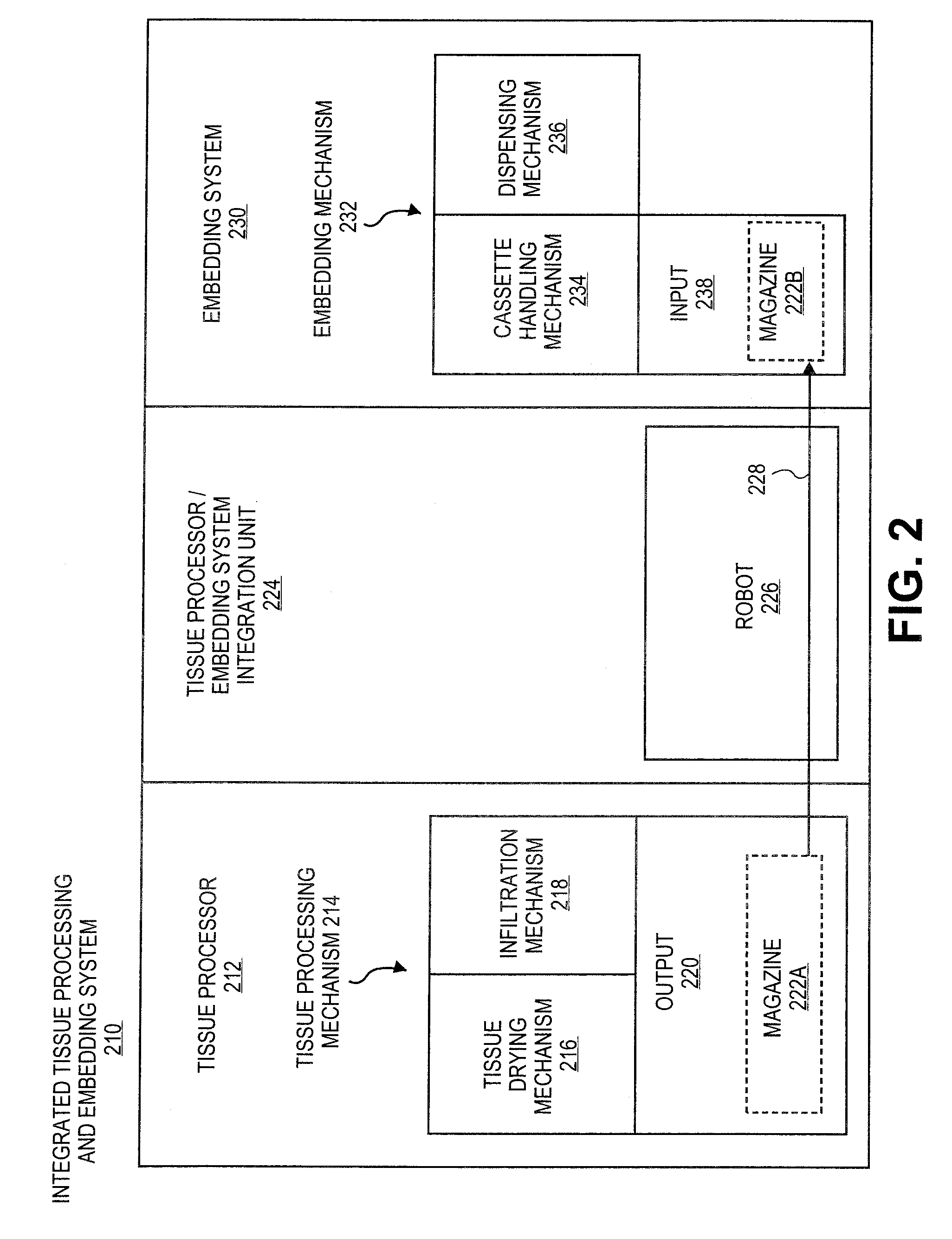
[0033]FIG. 2 is a block diagram of integrated tissue processing and embedding system 210. For convenience, the integrated tissue processing and embedding system may be referred to simply as an integrated system.

[0034]The integrated system includes tissue processor 212, embedding system 230, and tissue processor / embedding system integration unit 224. The tissue processor and the embedding system may perform their individual functions according to known instruments. As such, a detailed understanding of the inner mechanisms or workings of the tissue processor and the embedding system are not necessary. Accordingly, only a brief description will be provided.

[0035]Initially, a magazine having multiple cassettes, for example, may be input into the tissue processor through an input (not shown). Each of the cassettes may have a tissue, which has potentially been grossed and / or fixated.

[0036]FIG. 3 is a representative embodiment of cassette 340 which is suitable. In this embodiment, cassette...

second embodiment

[0066]FIG. 6 is a block diagram of integrated tissue processing and embedding system 610, which for convenience may simply be referred to as integrated system. The integrated system includes tissue processor 212 and embedding system 230. The tissue processor and the embedding system, and their components and functions, may optionally be similar to, or the same as, those of FIG. 2. To avoid obscuring the description, these aspects will not be repeated.

[0067]The integrated system also includes tissue processor / embedding system integration unit 624, or simply the integration unit. In an embodiment where a controller is linked to a tissue processor and an embedding system to control the transfer of a magazine(s) from the tissue processor to the embedding system, the controller may also be electronically linked to the integration unit.

[0068]Integration unit 624 has robot 626. Robot 626, and its components and functions, may be similar to those of robot 226 of FIG. 2, with a few notable e...

fifth embodiment

[0140]FIG. 11 is a block diagram of integrated tissue processing and embedding system 1110, which may be referred to simply as the integrated system, along with an embedding system 230. The integrated system includes tissue processor 212, and tissue processor / embedding system integration unit 1124, which for may be referred to simply as the integration unit. The tissue processor has output 220. The integration unit has storage location 1124 and robot 1126.

[0141]In one or more embodiments, integration unit 1124 and robot 1126 may be functionally or operatively coupled or connected with tissue processor 212, but not with embedding system 230. In one or more embodiments, as shown by arrow 1157, the robot may transfer magazine 222A from output 220 of the tissue processor to storage location 1156 of the integration unit as magazine 222B. Magazine 222B may be transferred from the storage location to the embedding system manually.


PUM


Abstract

Apparatus and methods for integrating tissue processors and embedding systems. An apparatus, of one aspect, includes a robot. The robot has a work envelope that encompasses a location having a tissue holder and an input of an embedding system. The tissue holder has at least one processed tissue. The robot is configured to transfer the tissue holder from the location to the input of the embedding system. A method, of one aspect, may include moving a robot to a location having a tissue holder. The tissue holder may have at least one processed tissue. The robot may engage with the tissue holder at the location. The robot may move the tissue holder from the location to an input to an embedding system. The robot may disengage from the tissue holder at the input to the embedding system. Other methods, apparatus, and systems are also disclosed.

Description

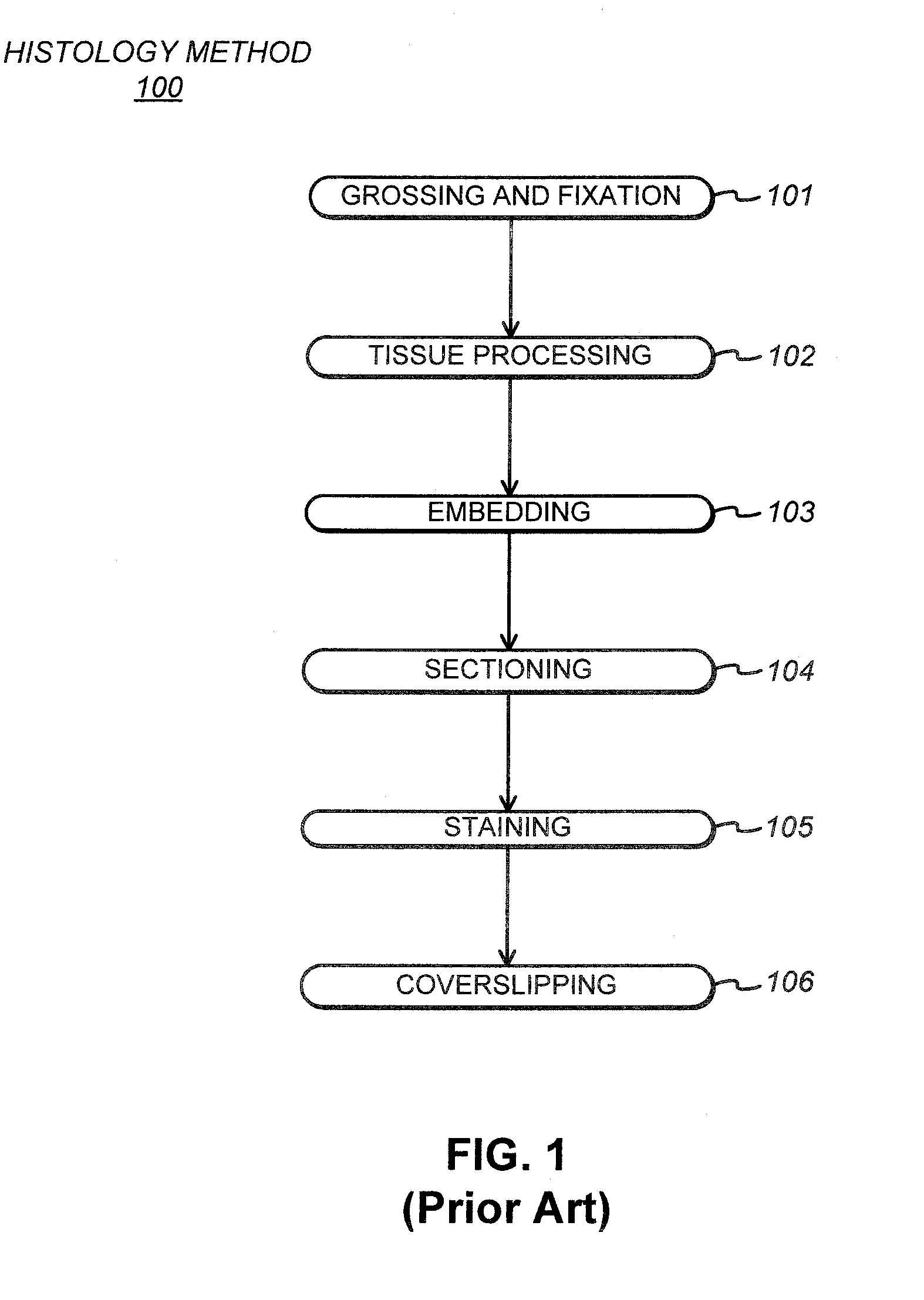
BACKGROUND[0001]1. Field[0002]Integrated tissue processing and embedding systems, and methods.[0003]2. Background Information[0004]Histology is a science or discipline associated with the processing of tissue for examination or analysis. The examination or analysis may be of the cellular morphology, chemical composition, tissue structure or composition, or other tissue characteristics. Histology is used in research, diagnostic, and other applications.[0005]FIG. 1 is a block flow diagram of an embodiment of histological method 100. This is just one representative histological method. Various modifications of this histological method exist, such as by adding, removing, and / or rearranging operations.[0006]At block 101, grossing and fixation may be performed on tissue. The tissue may represent tissue samples or specimens taken during biopsies, autopsies, surgeries, or other tissue extractions. The tissue may also represent a pellet of tissue. Grossing the tissue may potentially include ...

Claims


Application Information

Patent Timeline
Patent Type & Authority Applications(United States)
IPC IPC(8): G06F19/00
CPCG01N1/36B25J11/00G05B15/02Y10S901/02B08B7/04B08B7/00B08B3/022
Inventor LEFEBVRE, GILLESEVANS, ROBERT E.
Owner SAKURA FINETEK U S A
Learn More