Electronic Anesthesia Delivery Apparatus

a technology of electronic anesthesia and delivery apparatus, which is applied in the direction of local control/monitoring, operating means/releasing devices of valves, respirators, etc., can solve the problems of loss of efficiency of wicking material, loss of accuracy of vaporizers, and specifications of vaporizers on the market today

Active Publication Date: 2011-03-10
VETLAND MEDICAL SALES & SERVICES
View PDF9 Cites 32 Cited by
  • Summary
  • Abstract
  • Description
  • Claims
  • Application Information

AI Technical Summary

Problems solved by technology

One problem associated with the above mentioned traditional vaporizers is that being mechanical, the vaporizer loses accuracy due to wear of the internal mechanical thermostats and loss of efficiency of the wicking material.
Another problem is the specifications for vaporizers on the market today.
Yet another problem is their up-front expense and the inability to be easily converted to new drug types.
Such design is not cost effective.
Another weakness of the traditional vaporizers is their percentage of anesthesia output with respect to flow over a time period.
Another problem is that physicians must manually operate mechanical valves and dials on anesthesia machines.
This is difficult and requires the physician or assistant to look to different locations of the delivery apparatus to make adjustments.

Method used


Image

  • Electronic Anesthesia Delivery Apparatus
  • Electronic Anesthesia Delivery Apparatus
  • Electronic Anesthesia Delivery Apparatus

Examples


Embodiment Construction

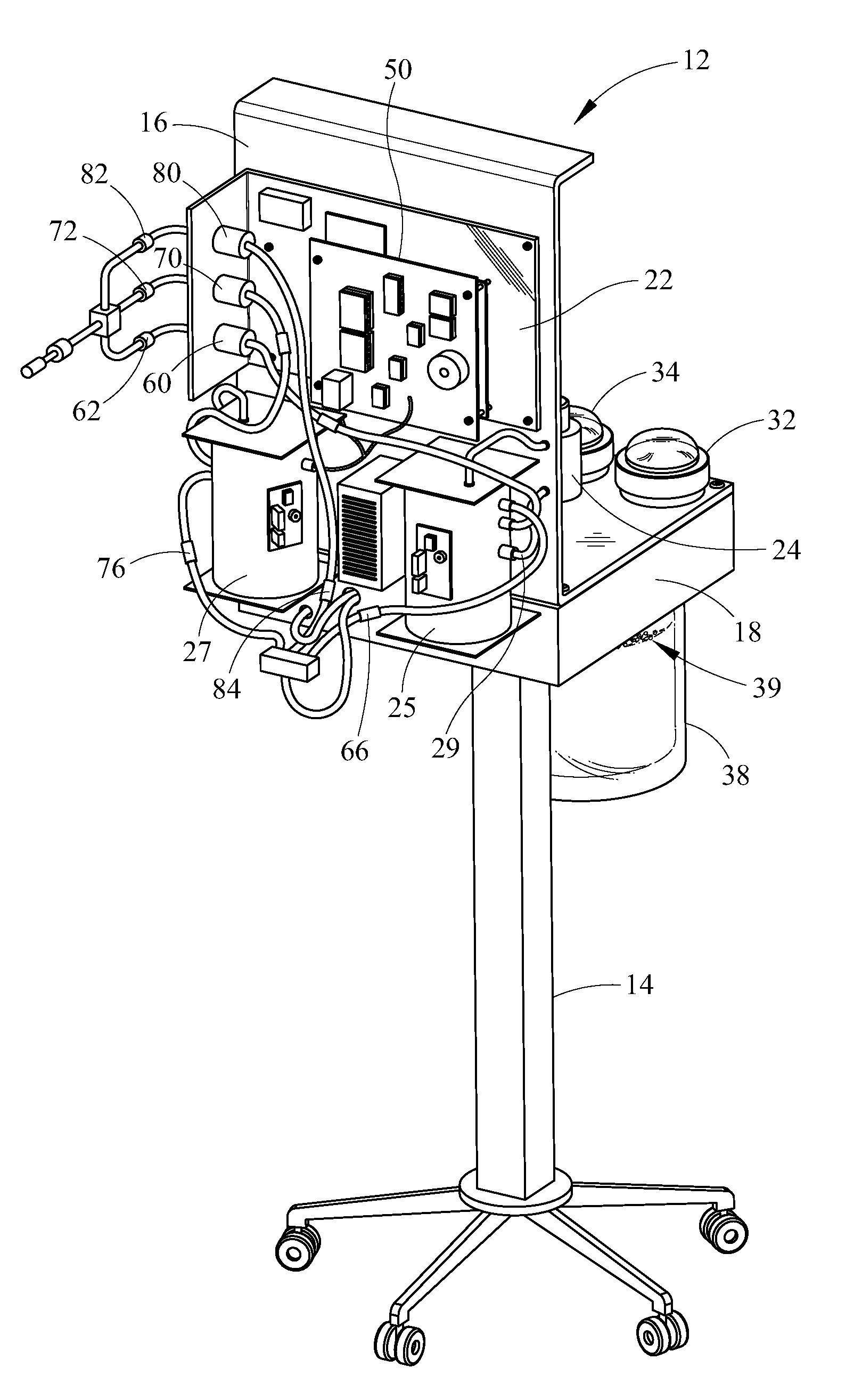
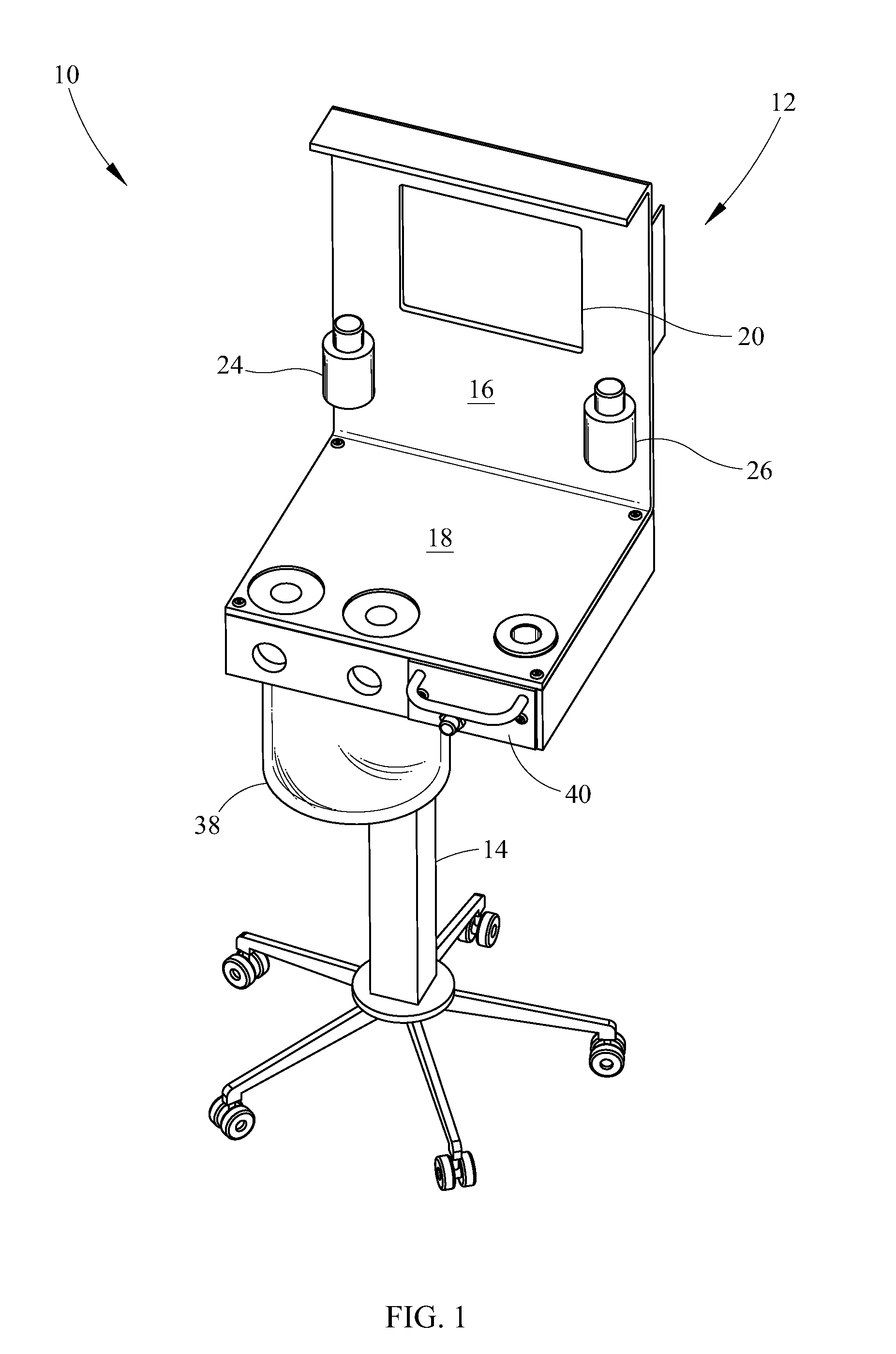
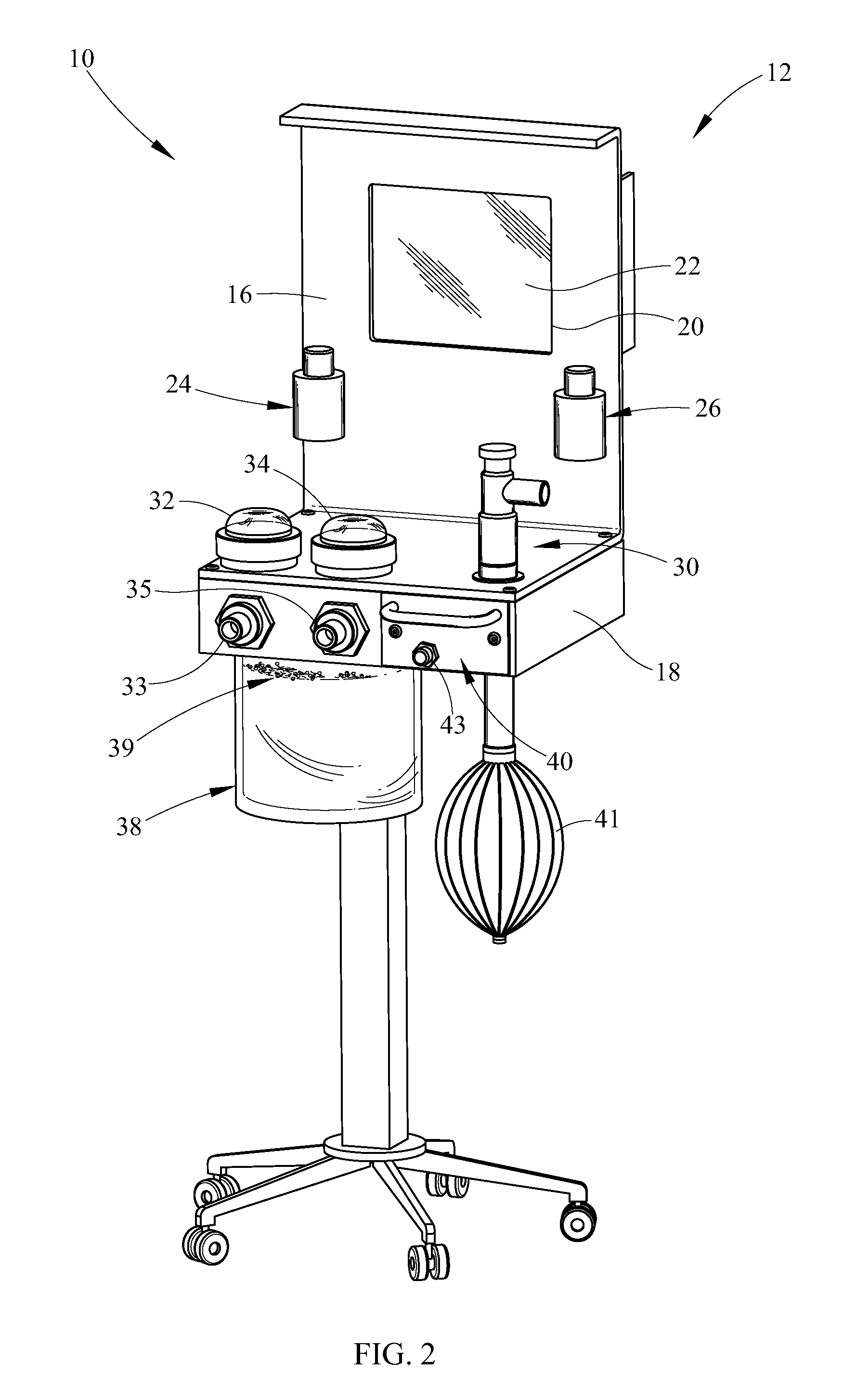
[0029]Referring now in detail to the drawings, wherein like numerals indicate like elements throughout the several views, there are shown in FIGS. 1-8 various aspects of an electronic anesthesia delivery apparatus which provides several advantages over the prior art. First, the novel electronic anesthesia delivery apparatus utilizes a touchscreen graphics display to electronically control the delivery of anesthesia, or oxygen or other carrier gas alone, to a patient. Second, the device comprises a vaporizer which does not require a wicking material in order to vaporize an anesthetic agent and therefore allows easy conversion from one anesthetic agent to another. Third, the anesthesia delivery apparatus provides improved accuracy in controlling anesthesia output over a range of oxygen flows. For purpose of the following description, anesthesia is meant to comprise an anesthetic agent and a carrier gas such as oxygen, air, nitrous oxide or other suitable carrier. For reasons of clarit...


PUM


Abstract

An electronic anesthesia delivery apparatus for mixing a carrier gas and first and second anesthetic agents comprises a chassis having an electronic vaporizer, the vaporizer having a first anesthetic chamber and a second anesthetic chamber retaining the first anesthetic agent and the second anesthetic agent, a carrier gas input port in flow communication with the first anesthetic chamber and the second anesthetic chamber, a precision orifice and an electronic control valve corresponding to each of the chambers being downstream of the gas input port, each of the chambers having a conduit in flow communication with the carrier gas input port, each of the conduits extending into each of the chambers below an upper level of anesthetic agent, wherein the carrier gas passes through a porous diffuser near an end of the conduit and bubbles through the anesthetic agent, the chamber further comprising an anesthetic gas outlet port, an electronic touchscreen display for controlling carrier gas flow rate to the first anesthetic chamber and the second anesthetic chamber, the electronic touchscreen display further allowing control of concentrations of the anesthetic agent in an anesthesia to a patient by intermittently opening and closing of the electronic control valve, a circuit board having an input / output portion, the circuit board in electronic communication with the electronic touchscreen display, the input / output portion receiving temperature of the anesthetic agent, the electronic anesthesia delivery apparatus allowing use of a first anesthetic agent while a second anesthetic agent is one of either replaced or substituted in the second chamber.

Description

CROSS REFERENCES TO RELATED APPLICATIONS[0001]This application is a Continuation-In-Part application claiming priority to and benefit from, currently pending, U.S. patent application Ser. No. 11 / 031,661, filed on Jan. 7, 2005.STATEMENT REGARDING FEDERALLY SPONSORED RESEARCH OR DEVELOPMENT[0002]None.REFERENCE TO SEQUENTIAL LISTINGS, ETC.[0003]None.BACKGROUND[0004]1. Field of the Invention[0005]The present invention provides an anesthesia delivery apparatus. More specifically, the present invention comprises an electronic anesthesia delivery apparatus for controlling delivery of at least two anesthetic agents from at least two respective diffusers to a patient.[0006]2. Description of the Related Art[0007]Standard anesthesia delivery machines utilize a plurality of mechanical components to deliver a measured amount of anesthesia to a patient, for example, an animal. Many of these standard devices include an oxygen flow meter, a pressure gauge, and a vaporizer. Such vaporizers typically...

Claims


Application Information

Patent Timeline
Patent Type & Authority Applications(United States)
IPC IPC(8): A61M16/01G16H20/40
CPCA61M16/0051A61M16/209A61M16/009A61M16/01A61M16/18A61M16/22A61M2016/0039A61M2205/505A61M2205/8206A61M2205/8237A61M2209/084G06F19/3406G06F19/3481A61M16/1015A61M16/0078A61M16/0093A61M16/202A61M16/024G16H40/63G16H20/40
Inventor RUMPH, BRADHOEHLER, TOMLERMAN, MARK
Owner VETLAND MEDICAL SALES & SERVICES
Why Eureka
Try Eureka