Charge controller

Inactive Publication Date: 2011-03-10
RICOH ELECTRONIC DEVICES CO LTD
View PDF2 Cites 10 Cited by
  • Summary
  • Abstract
  • Description
  • Claims
  • Application Information

AI Technical Summary

Benefits of technology

[0014]wherein “I” represents the set current value, “Ilim” representing a control parameter, “I1” represents the detected output current, and “I2” represents the detected charge current.
[0015]In another aspect of the disclosure, the charge controller includes a power supply circuit and a battery charge circuit. The power supply circuit has an input terminal thereof connected to an input voltage and an output terminal thereof connected to a load, and converts the input voltage into an output voltage for supply to the load at the output terminal. The power supply circuit includes an output current detection circuit and an output current limiting circuit. The output current detection circuit detects an output current supplied through the power supply circuit. The output current limiting circuit limits the output current below a maximum output current limit. The battery charge circuit has an input terminal thereof connected to the output terminal of the

Problems solved by technology

A problem encountered by the charge controller is that it fails to supply the secondary battery with a sufficient current when the electronic device is in use and consumes power, where the external power source has a limited maximum current output capacity equivalent to, or slightly greater than, a maximum rated current of the load circuitry.
These conventional methods have several drawbacks due to the operating principle that the sum of the load current and the charge current always matches the maximum current limit of the AC adapter.
One common drawback is that the charge control circuit has substantially no tolerance for excessive current where the current rating of the AC adapter is relatively small.
That is, a significant decline in the output voltage of the AC adapter can occur to cause malfunctioning of the device, when the load current increases so rapidly that the circuit fails to cancel the increase in the load current by reducing the charge current.
Another common drawback is that the charge current can become significantly large to exceed a rated maximum limit of the secondary battery where the current rating of the AC adapter itself is relatively large.
In addition to those drawbacks that may result when the secondary battery is in a normal operating state, still another drawback can also occur where the battery is in an abnormal state, e.g., over-discharged or overheated.
An over-discharged or overheated secondary battery is required to be charged with a current sufficiently smaller than normal, since charging with a large current can reduce the life of the battery in the abnormal condition.
However, the conventional circuit cannot adjust the charge current depending on the operating condition of the battery, and thus has the risk of damaging the battery during charge.

Method used


Image

  • Charge controller
  • Charge controller
  • Charge controller

Examples


second embodiment

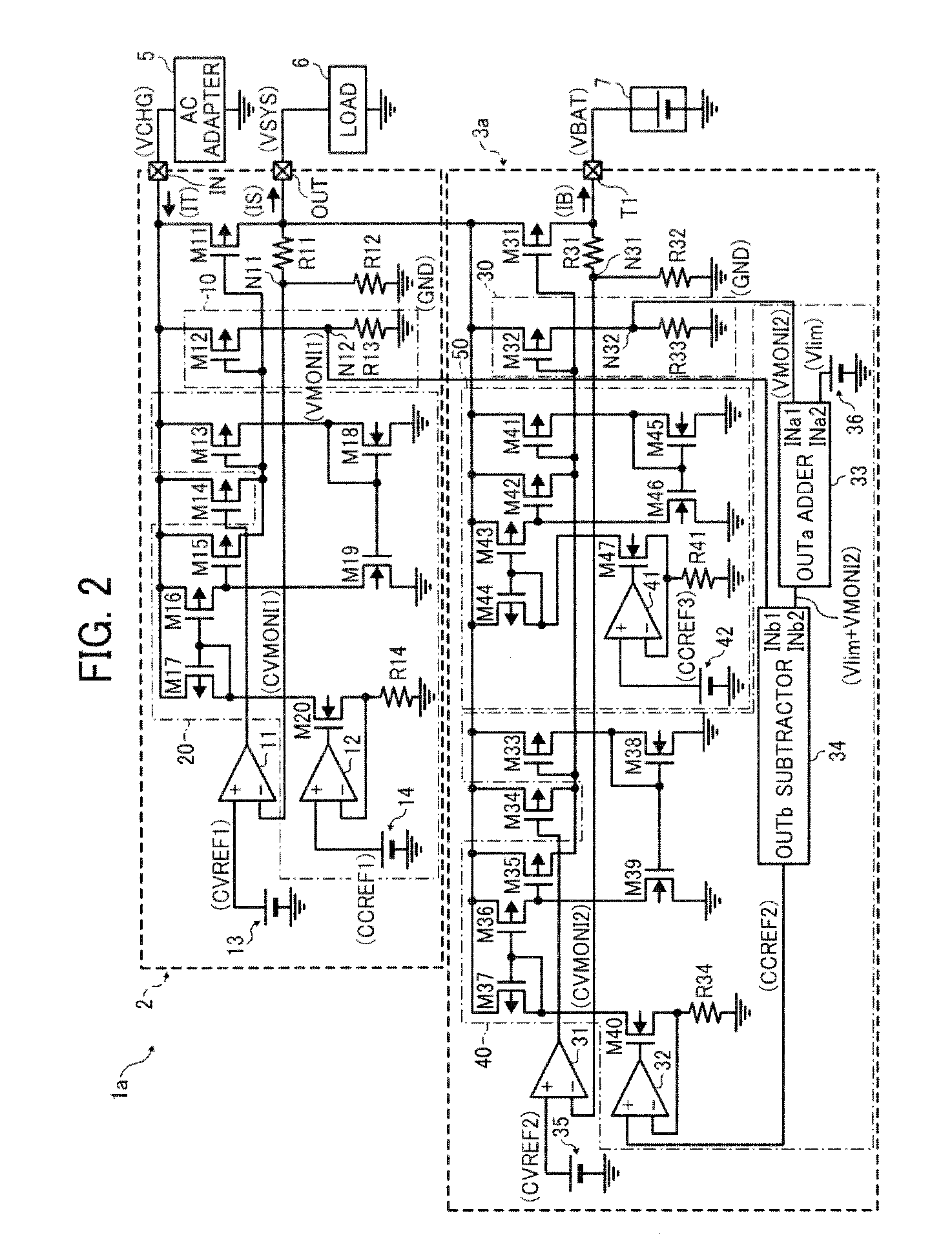
[0071]FIG. 2 is a circuit diagram schematically illustrating a charge controller 1a according to this patent specification.

[0072]As shown in FIG. 2, the overall configuration of the charge controller 1a is similar to that depicted in FIG. 1, including a power supply circuit 2 with an input terminal IN connected to an AC adapter 5, and an output terminal OUT connected to a load circuit 6, as well as a battery charge circuit 3a with an input terminal connected to the output terminal OUT and an output terminal T1 connected to a rechargeable, secondary battery 7.

[0073]The power supply circuit 2 comprises a series voltage regulator that converts an input voltage VCHG input to the input terminal IN from the AC adapter 5 to generate a constant output voltage VSYS for supply to the load circuit 6 at the output terminal OUT. The battery charge circuit 3a derives power from the power supply circuit 2 to charge the secondary battery 7 with a charge current IB at a battery voltage VBAT.

[0074]Un...

third embodiment

[0080]FIG. 3 is a circuit diagram schematically illustrating a charge controller 1b according to this patent specification.

[0081]As shown in FIG. 3, the overall configuration of the charge controller 1b is similar to that depicted in FIG. 1, including a power supply circuit 2 with an input terminal IN connected to an AC adapter 5 and an output terminal OUT connected to a load circuit 6, as well as a battery charge circuit 3b with an input terminal connected to the output terminal OUT and an output terminal T1 connected to a rechargeable, secondary battery 7.

[0082]The power supply circuit 2 comprises a series voltage regulator that converts an input voltage VCHG input to the input terminal IN from the AC adapter 5 to generate a constant output voltage VSYS for supply to the load circuit 6 at the output terminal OUT. The battery charge circuit 3b derives power from the power supply circuit 2 to charge the secondary battery 7 with a charge current IB at a battery voltage VBAT.

[0083]Unl...


PUM


Abstract

A charge controller includes a power supply circuit and a battery charge circuit. The power supply circuit converts the input voltage into an output voltage for supply to the load at the output terminal. The power supply circuit includes an output current detection circuit and an output current limiting circuit. The output current detection circuit detects an output current supplied through the power supply circuit. The output current limiting circuit limits the output current below a maximum output current limit. The battery charge circuit derives power from the power supply circuit to charge a secondary battery. The battery charge circuit includes a charge current detection circuit and a charge current setting circuit. The charge current detection circuit detects a charge current supplied to the secondary battery. The charge current setting circuit regulates the charge current to a set current value.

Description

BACKGROUND OF THE INVENTION[0001]1. Technical Field[0002]The present invention relates to a charge controller for rechargeable, secondary batteries, and more particularly, to a charge controller that can effectively manage electricity from a power source of limited current capacity to charge a secondary battery while supplying power to load circuitry.[0003]2. Discussion of the Background[0004]Rechargeable, secondary batteries are commonly employed in portable electronic devices, such as laptop computers and cellular phones. Typically, battery-powered electronic equipment includes charge control circuitry that simultaneously charges the secondary battery and supplies power to load circuitry whenever the device is connected to an external power source, for example, an AC adapter. A problem encountered by the charge controller is that it fails to supply the secondary battery with a sufficient current when the electronic device is in use and consumes power, where the external power sour...

Claims


Application Information

Patent Timeline
IPC IPC(8): H02J7/04
CPCH02J7/0068H02J7/047H02J7/045H02J7/04H02J7/00714H02J7/007194H02J7/007192
Inventor ASHIDA, KEIICHI
Owner RICOH ELECTRONIC DEVICES CO LTD
Why Eureka
Try Eureka