Headphone, headphone stand and headphone system

a headphone stand and headphone technology, applied in the direction of earpiece/earphone attachment, transducer details, electrical transducers, etc., can solve the problems of small electric power, difficult to make the surface of the feeding coil and the receiving coil face each other, and virtually difficult to make the loading coil incorporated in the headphone, so as to achieve efficient and safe wireless power feeding

Active Publication Date: 2013-08-29
TDK CORPARATION
View PDF0 Cites 45 Cited by
  • Summary
  • Abstract
  • Description
  • Claims
  • Application Information

AI Technical Summary

Benefits of technology

[0016]According to the present invention, a headphone system capable of performing wireless power feeding efficiently and safely can be provided.

Problems solved by technology

The type (B) utilizing radio wave is available in a long range; however, it has small electric power.
However, in the configuration disclosed in Jpn. Pat. Appln. Laid-Open Publication No. 2011-83078, the sizes of the units 101, 102, and 103 tend to increase, and it is difficult to make coil surfaces of a feeding coil and a receiving coil face each other.
Particularly, in the configuration disclosed in Jpn. Pat. Appln. Laid-Open Publication No. 2011-83078, it is virtually difficult to make a coil (loading coil) incorporated in a headphone and a coil (receiving coil) incorporated in the unit 103 face each other properly.
Further, when a magnetic flux generated from a coil during wireless power feeding penetrates the charging circuit (secondary battery), eddy current occurs to cause the secondary battery to generate heat.

Method used


Image

  • Headphone, headphone stand and headphone system
  • Headphone, headphone stand and headphone system
  • Headphone, headphone stand and headphone system

Examples


first embodiment

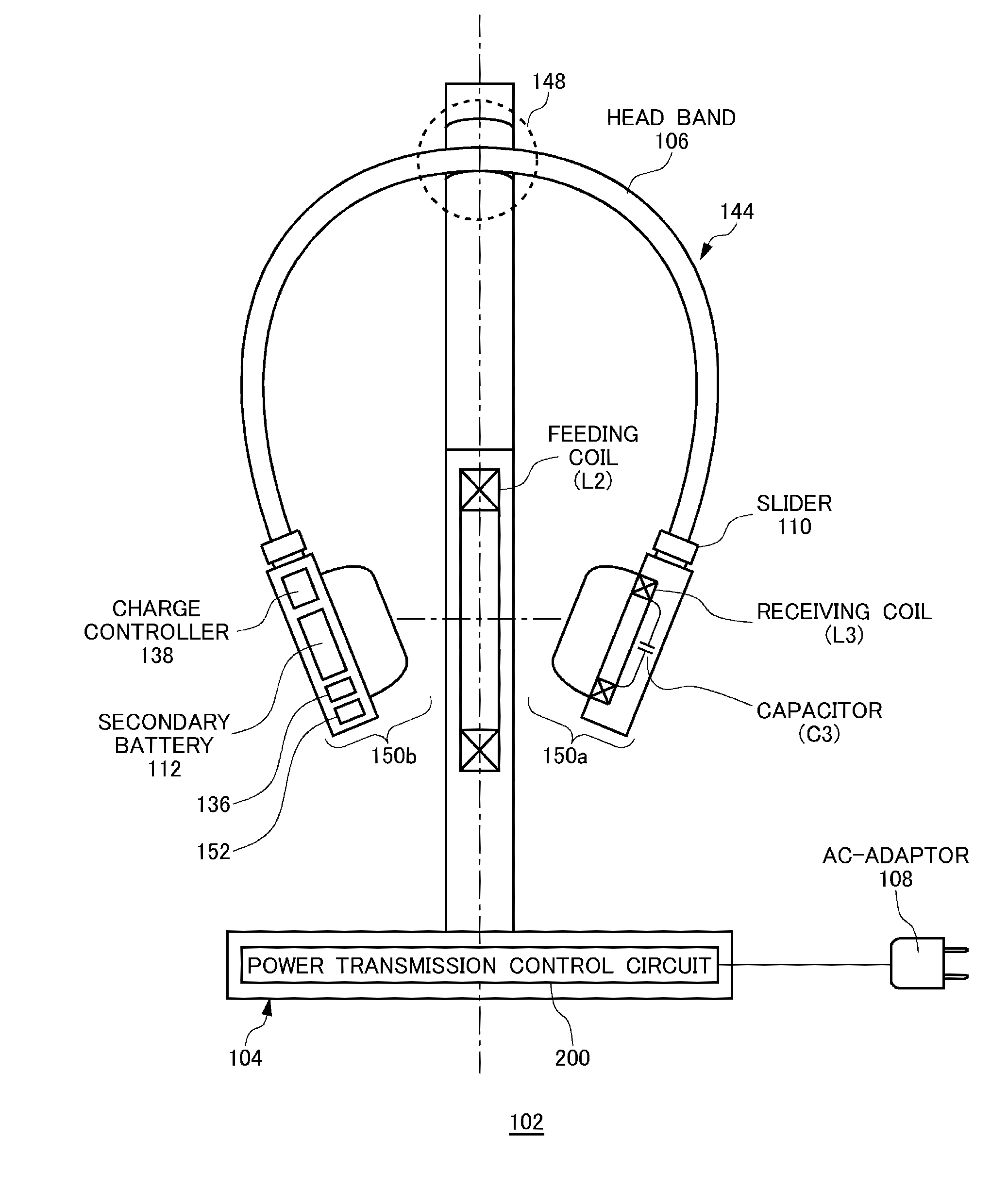
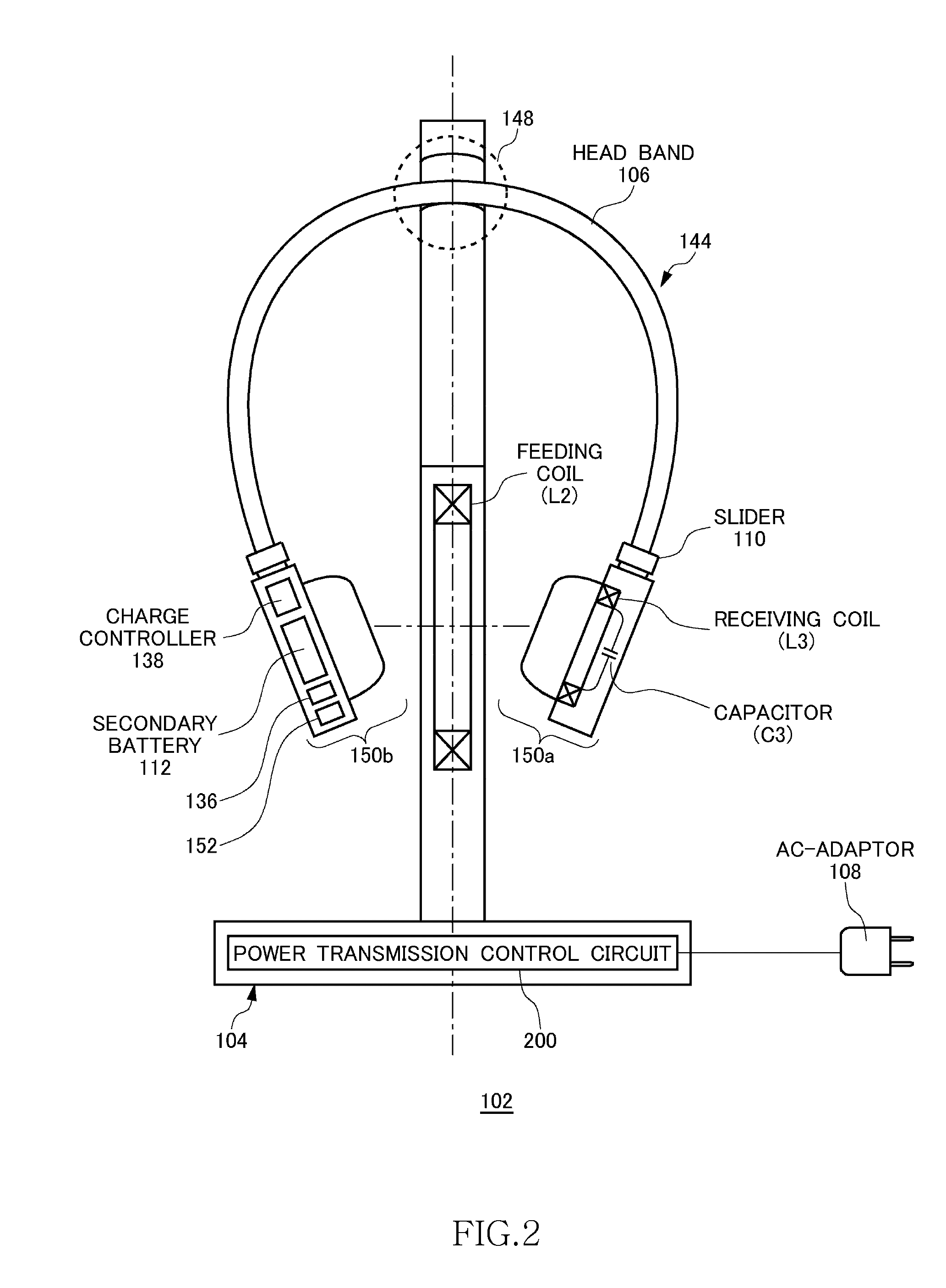
[0030]FIG. 2 is a front view of an outer appearance of a wireless headphone system 102 according to a first embodiment. The wireless headphone system 102 is one of applications of the wireless power transmission system 100 described with FIG. 1. The wireless headphone system 102 includes a headphone stand 104 and a headphone 144. The headphone stand 104 corresponds to the wireless power feeder 116, and the headphone 144 corresponds to the wireless power receiver 118. The headphone 144 includes two ear cups 150a, 150b and a head band 106. The head band 106 can be expanded / contracted by a slider 110. By hanging the headphone 144 from a hanging portion 148 of the headphone stand 104 at the head band 106, it is possible to stably set the headphone 144 in the headphone stand 104. The hanging portion 148 has a curved shape, which will be described later using FIG. 5. Upon setting of the headphone 144 in the headphone stand 104, power is fed by wireless from the headphone stand 104 to the ...

second embodiment

[0041]FIG. 7 is a front view of an outer appearance of the wireless headphone system 102 according to a second embodiment. The headphone stand 104 according to the second embodiment incorporates two feeding coils L2a and L2b. The feeding coil L2a is inclined by 30° with respect to a vertical line, and the feeding coil L2b is inclined by 30° with respect to the vertical line in an opposite direction to the feeding coil L2a. This configuration is because, when the headphone 144 is set, the ear cups 150a and 150b are each inclined by 30° with respect to the vertical line. It follows that the feeding coils L2a and L2b are arranged in a V-shape having an inclination of 60°. With the V-shape arrangement of the feeding coils L2, the coil surfaces of the feeding coil L2 and the receiving coil L3 become substantially parallel to each other, thereby further enhancing the power transmission efficiency. According to experiments made by the present inventors, the power transmission efficiency wa...


PUM


Abstract

A wireless headphone system 102 includes a headphone 144 and a headphone stand 104. The headphone 144 has two ear cups 150a and 150b. The ear cup 150a incorporates a receiving coil L3 and a capacitor C3. The ear cup 150b incorporates a charge controller 138 and a secondary battery 112. The headphone stand 104 incorporates a feeding coil L2. When the headphone 144 is set in the headphone stand 104, AC power is supplied from the feeding coil L2 to the receiving coil L3, and the secondary battery 112 of the headphone 144 is charged with the AC power.

Description

BACKGROUND OF THE INVENTION[0001]1. Field of the Invention[0002]The present invention relates to wireless power feeding and, more particularly, to a method of applying the wireless power feeding to a headphone system.[0003]2. Description of Related Art[0004]A wireless power feeding technique of feeding power without a power cord is now attracting attention. The current wireless power feeding technique is roughly divided into three: (A) type utilizing electromagnetic induction (for short range); (B) type utilizing radio wave (for long range); and (C) type utilizing resonance phenomenon of magnetic field (for intermediate range).[0005]The type (A) utilizing electromagnetic induction has generally been employed in familiar home appliances such as an electric shaver; however, it can be effective only in a short range. The type (B) utilizing radio wave is available in a long range; however, it has small electric power. The type (C) utilizing resonance phenomenon is a comparatively new te...

Claims


Application Information

Patent Timeline
Patent Type & Authority Applications(United States)
IPC IPC(8): H04R3/00
CPCH04R1/1008H04R3/00H04R1/1025
Inventor URANO, TAKASHISUZUKI, MITSUNARI
Owner TDK CORPARATION
Why Eureka
Try Eureka