Method and Pulse-Width-Modulated Current Control Circuit For Driving Inductive Loads in Motor Vehicles

a control circuit and inductive load technology, applied in the direction of braking system, magnetic body, instruments, etc., can solve the problems of increasing the the absolute precision level of the current measured value, etc., and achieve the effect of precise and reliable setting of the curren

Active Publication Date: 2011-03-10
CONTINENTAL TEVES AG & CO OHG
View PDF9 Cites 24 Cited by
  • Summary
  • Abstract
  • Description
  • Claims
  • Application Information

AI Technical Summary

Benefits of technology

[0014]An object of the present invention is to specify a method and a circuit arrangement for PWM current control with which more precise and reliable setting of a current can be performed.

Problems solved by technology

As a result, an absolute precision level of the current measured value—which precision level is limited owing to the usually in electronic components and in particular also in integrated analog components—can be increased even further.

Method used


Image

  • Method and Pulse-Width-Modulated Current Control Circuit For Driving Inductive Loads in Motor Vehicles
  • Method and Pulse-Width-Modulated Current Control Circuit For Driving Inductive Loads in Motor Vehicles
  • Method and Pulse-Width-Modulated Current Control Circuit For Driving Inductive Loads in Motor Vehicles

Examples


Embodiment Construction

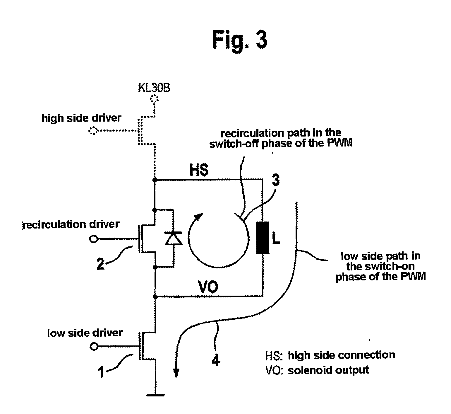
[0033]The schematic illustration of an output stage circuit which is illustrated in FIG. 3 and has a low side driver 1 and a recirculation driver 2 serves to explain the illustrated currents during PWM driving of the inductive load L. The load L is connected to ground via the low side driver 1, as a result of which the solenoid current rises exponentially when the maximum current has not yet been reached. In the switched-off state of the PWM driving means, the driver 2 is conductive, with the result that the decay current of the solenoid can flow through the recirculation path 3. This causes the current to decay exponentially.

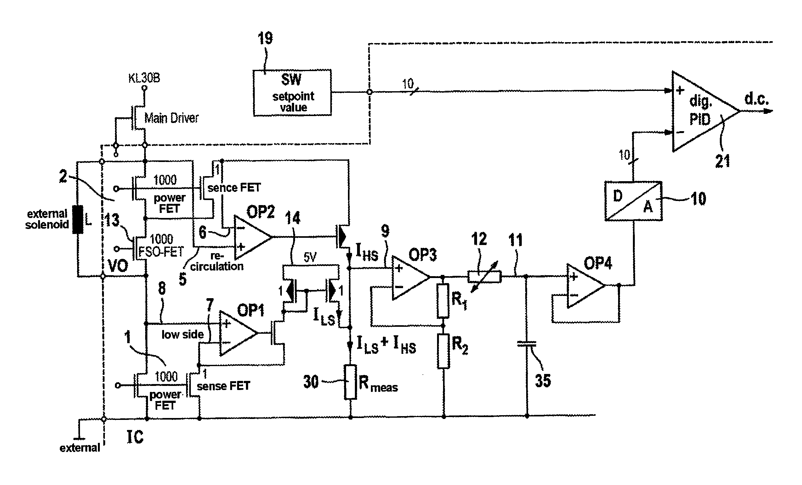
[0034]According to one exemplary embodiment of the invention, the current of the recirculation path 3 is also measured in order to measure the actual current of the current control means. This provides the advantage that current can be measured even with relatively short switch-on times of the PWM driving means.

[0035]In the circuit arrangement according to FIG....


PUM


Abstract

Method in which the current is measured inside an integrated PWM control circuit using at least one A / D converter which is likewise integrated in the circuit is described. The PWM controller is provided for the purpose of driving inductive loads and is arranged, in particular, in an electronic circuit of an electronic controller for a motor vehicle braking system. Before determining the actual current of the PWM controller, which is determined using the at least one A / D converter, the current is smoothed using a low-pass filter. A circuit arrangement for carrying out the above method and its use in electronic motor vehicle control systems is also described herein.

Description

CROSS REFERENCE TO RELATED APPLICATIONS[0001]This application is the U.S. national phase application of PCT International Application No. PCT / EP2007 / 054552, filed May 11, 2007, which claims priority to German Patent Application No. DE 102006023342.5, filed May 17, 2006 and German Patent Application No. DE 102006035564.4, filed Jul. 27, 2006, the contents of such applications being incorporated by reference herein in their entirety.BACKGROUND OF THE INVENTION[0002]1. Field of the Invention[0003]The invention relates to a pulse-width-modulated current control circuit for driving inductive loads in motor vehicles and to its use.[0004]2. Background of the Invention[0005]Electronic motor vehicle control units, such as controllers for ABS and / or ESP motor vehicle brake control units, comprise multiply redundant microprocessor systems and additional power circuits for driving loads such as, for example, the electromagnetic valve solenoids which are necessary for regulating pressure. Modern...

Claims


Application Information

Patent Timeline
Patent Type & Authority Applications(United States)
IPC IPC(8): G01R1/14
CPCB60T8/36B60T2270/411G01R19/0092H02M2003/1555H01F2007/1866H01F2007/1888H02M2001/0009H01F7/1811H02M1/0009H02M3/1555
Inventor JAGER, MARKUSOEHLER, PETERMICHEL, FRANKHEINZ, MICHAFEY, WOLFGANGSCHMITZ, AXELJOECKEL, WOLFGANG
Owner CONTINENTAL TEVES AG & CO OHG
Why Eureka
Try Eureka