Adaptive common mode bias for differential amplifier input circuits

a differential amplifier and input circuit technology, applied in differential amplifiers, amplifiers with semiconductor devices/discharge tubes, amplifier details, etc., can solve the problems of non-linear operation of differential amplifier stages, non-linear response, complex problems continue to rise to the forefront, etc., and achieve the effect of expanding the input common mode rang

Inactive Publication Date: 2011-03-10
GLOBALFOUNDRIES INC
View PDF10 Cites 38 Cited by
  • Summary
  • Abstract
  • Description
  • Claims
  • Application Information

AI Technical Summary

Problems solved by technology

As the demand for bandwidth and gain requirements in serial link receivers increases, complex problems continue to rise to the forefront.
For example, input signals of varying ranges often lead to non-linear operation of differential amplifier stages.
These non-linear responses are caused by limited common mode range of the differential amplifier.
As common mode requirements go to extreme highs and lows, as compared to the power supply of the amplifier, biasing problems associated with the differential input transistors and current sources of the amplifier arise.
These biasing problems lead to non-linear responses and inaccurate differential gain outputs of the differential amplifier.
However, adding additional circuitry causes processing speed to decrease and the size of the devices to increase.
Processing speed decreasing with device size increasing creates an even greater problem for applications having increased bandwidth and gain requirements.
Further, level shifting does not extend common mode range.

Method used


Image

  • Adaptive common mode bias for differential amplifier input circuits
  • Adaptive common mode bias for differential amplifier input circuits
  • Adaptive common mode bias for differential amplifier input circuits

Examples


Embodiment Construction

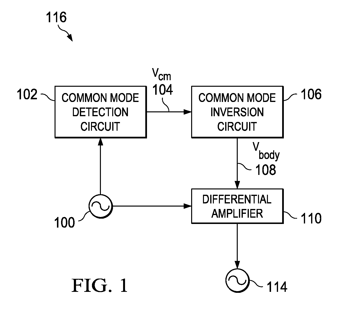
[0020]With reference now to the figures, and particularly with reference to FIG. 1, a block diagram of circuit system 116 is depicted in accordance with an illustrative embodiment. Differential signal 100 is received by both common mode detection circuit 102 and differential amplifier 110. Common mode detection circuit 102 monitors differential signal 100 to determine common mode voltage 104 of differential signal 100. Common mode voltage 104 passes through common mode inversion circuit 106 creating body voltage 108. Body voltage 108 bears an inverse relationship to common mode voltage 104, thereby extending the common mode range of differential amplifier 110. Differential amplifier 110 produces output signal 114. While circuit system 116 is comprised of common mode detection circuit 102, common mode inversion circuit 106, and differential amplifier 110 in this illustrative embodiment, additional circuitry may be added to circuit system 116.

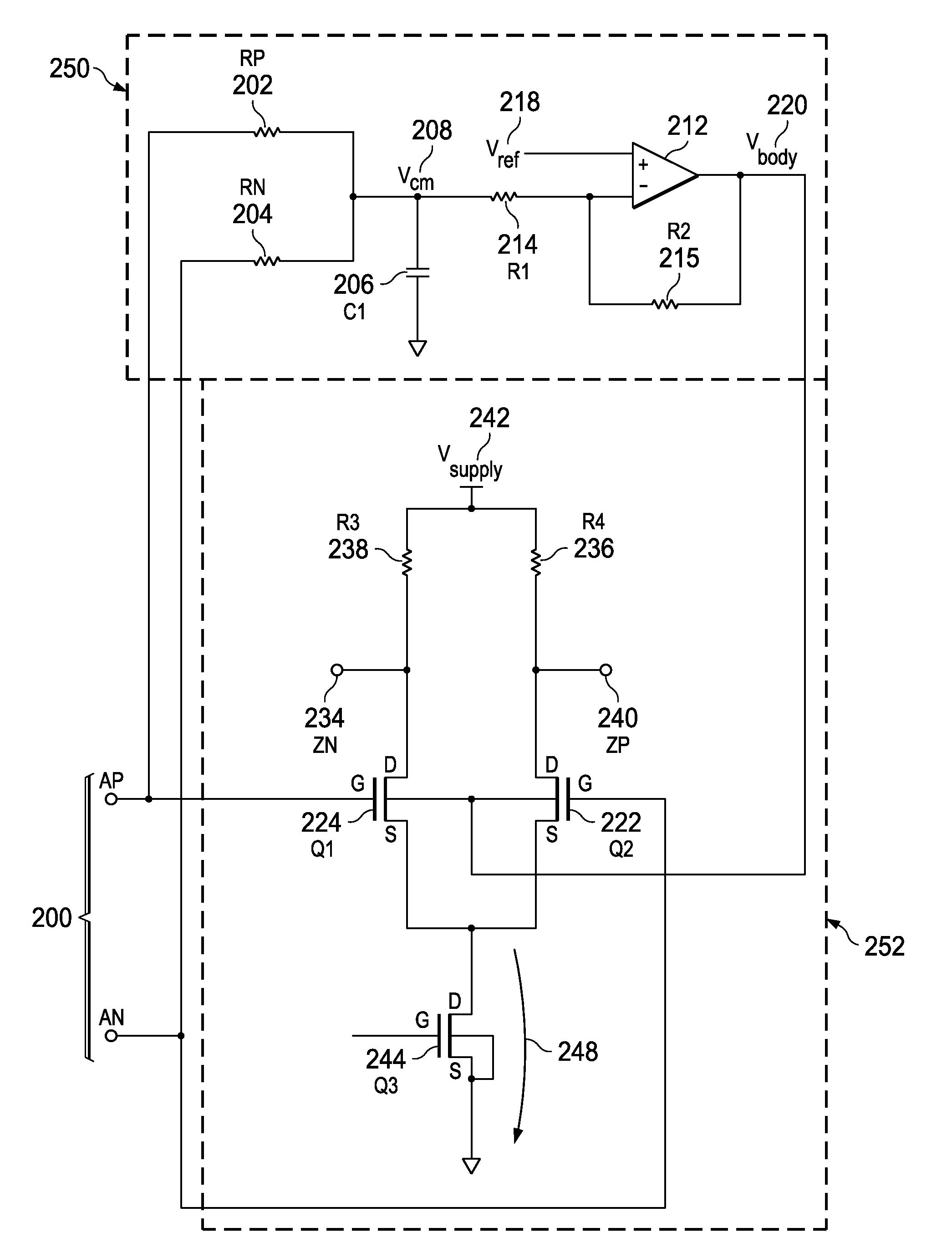
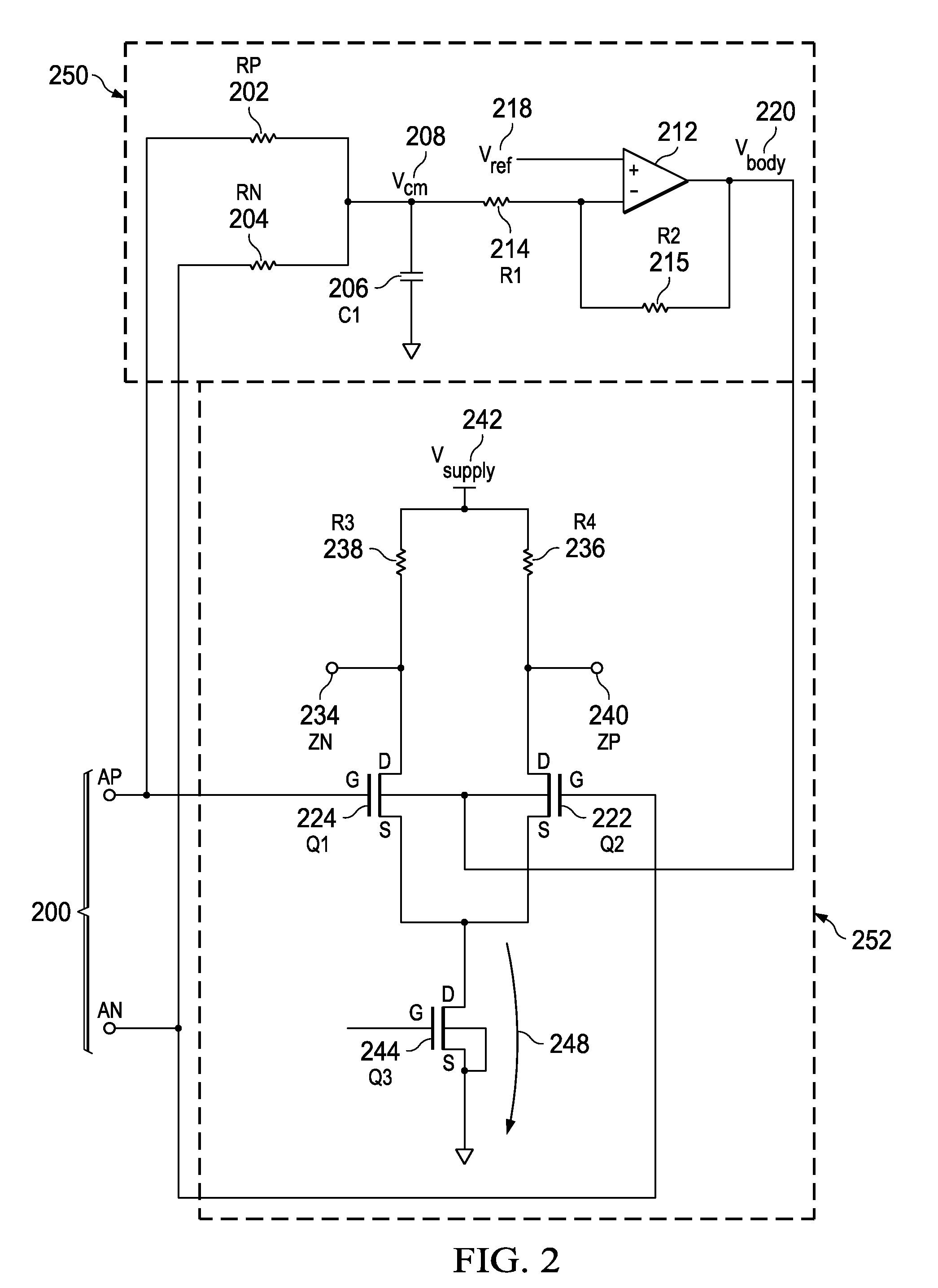
[0021]Turning now to FIG. 2, a circuit dia...


PUM


Abstract

A method and apparatus for extending the common mode range of a differential amplifier. A circuit has a common mode detection circuit, a common mode voltage inversion circuit, and a differential amplifier. The common mode detection circuit receives a differential signal and detects a common mode voltage. The common mode voltage inversion circuit is coupled to the common mode detection circuit. The common mode voltage inversion circuit has an input node that receives the common mode voltage and an output node that outputs body voltage, wherein the common mode voltage inversion circuit creates an inverse relationship between the common mode voltage and the body voltage. The differential amplifier includes a differential pair of transistors that have a pair of body terminals coupled to the output node of the common mode voltage inversion circuit.

Description

BACKGROUND[0001]1. Field[0002]The disclosure relates generally to differential amplifiers and, more specifically, to body biasing circuitry for differential amplifiers.[0003]2. Description of the Related Art[0004]As the demand for bandwidth and gain requirements in serial link receivers increases, complex problems continue to rise to the forefront. For example, input signals of varying ranges often lead to non-linear operation of differential amplifier stages. These non-linear responses are caused by limited common mode range of the differential amplifier. Design engineers continually seek to solve problems relating to common mode range of their devices.[0005]In a differential amplifier, the input common mode range refers to the range of differential input signals over which a differential amplifier maintains a linear response, including differential gain. In its simplest form, a differential amplifier has a pair of differential input transistors that receive a differential signal. ...

Claims


Application Information

Patent Timeline
Patent Type & Authority Applications(United States)
IPC IPC(8): H03F3/45
CPCH03F1/3211H03F3/45183H03F3/45632H03F2203/45342H03F2203/45078H03F2203/45292H03F2203/45008
Inventor CRANFORD, JR., HAYDEN C.RASMUS, TODD M.STEVENS, JOSEPH M.
Owner GLOBALFOUNDRIES INC
Why Eureka
Try Eureka