Image forming device and cartridge

a technology of forming device and driving gear, which is applied in the direction of instruments, electrographic process equipment, optics, etc., can solve the problems of soiling the user's hand or clothes, clogging the recessed part of the driven gear, etc., and achieve the effect of enhancing usability

Active Publication Date: 2011-03-10
BROTHER KOGYO KK
View PDF12 Cites 24 Cited by
  • Summary
  • Abstract
  • Description
  • Claims
  • Application Information

AI Technical Summary

Benefits of technology

[0011]Aspects of the present invention are advantageous in that usability can be enhanced in a configuration where a cartridge is detachably attachable to a device main body having a driving source to transmit a driving force to the cartridge.

Problems solved by technology

In this case, a user may soil the user's hand or clothes with the grease exposed to the outside of the development cartridge.
Further, foreign material may adhere to the grease, thereby clogging the recessed part of the driven gear.

Method used


Image

  • Image forming device and cartridge
  • Image forming device and cartridge
  • Image forming device and cartridge

Examples


Embodiment Construction

[0025]Hereafter, an embodiment according to the invention will be described with reference to the accompanying drawings. In the following, explanations are made with reference to directions defined in the drawings.

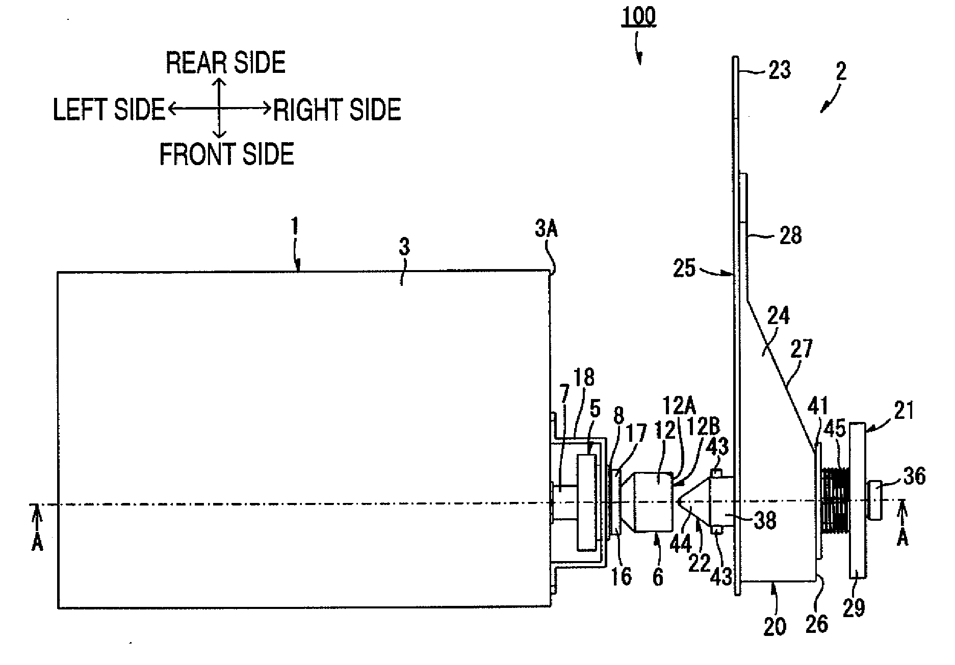
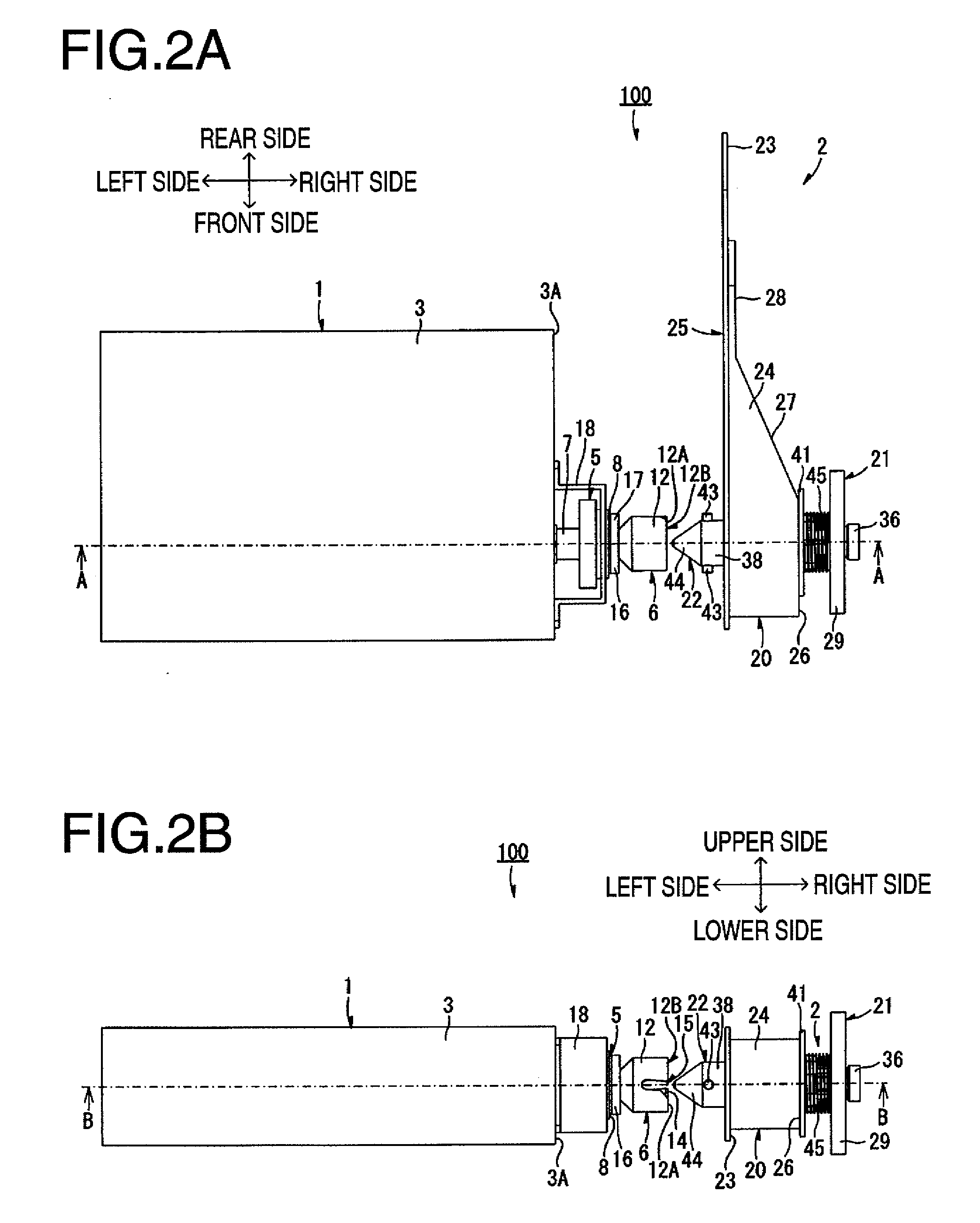
[0026]An image forming device 100 (see FIGS. 2A and 2B) is, for example, a laser printer. As shown in FIGS. 2A and 2B, the image forming device 100 includes a cartridge 1 and a device main body 2. In the following, the cartridge 1 and the device main body 2 are explained in this order.

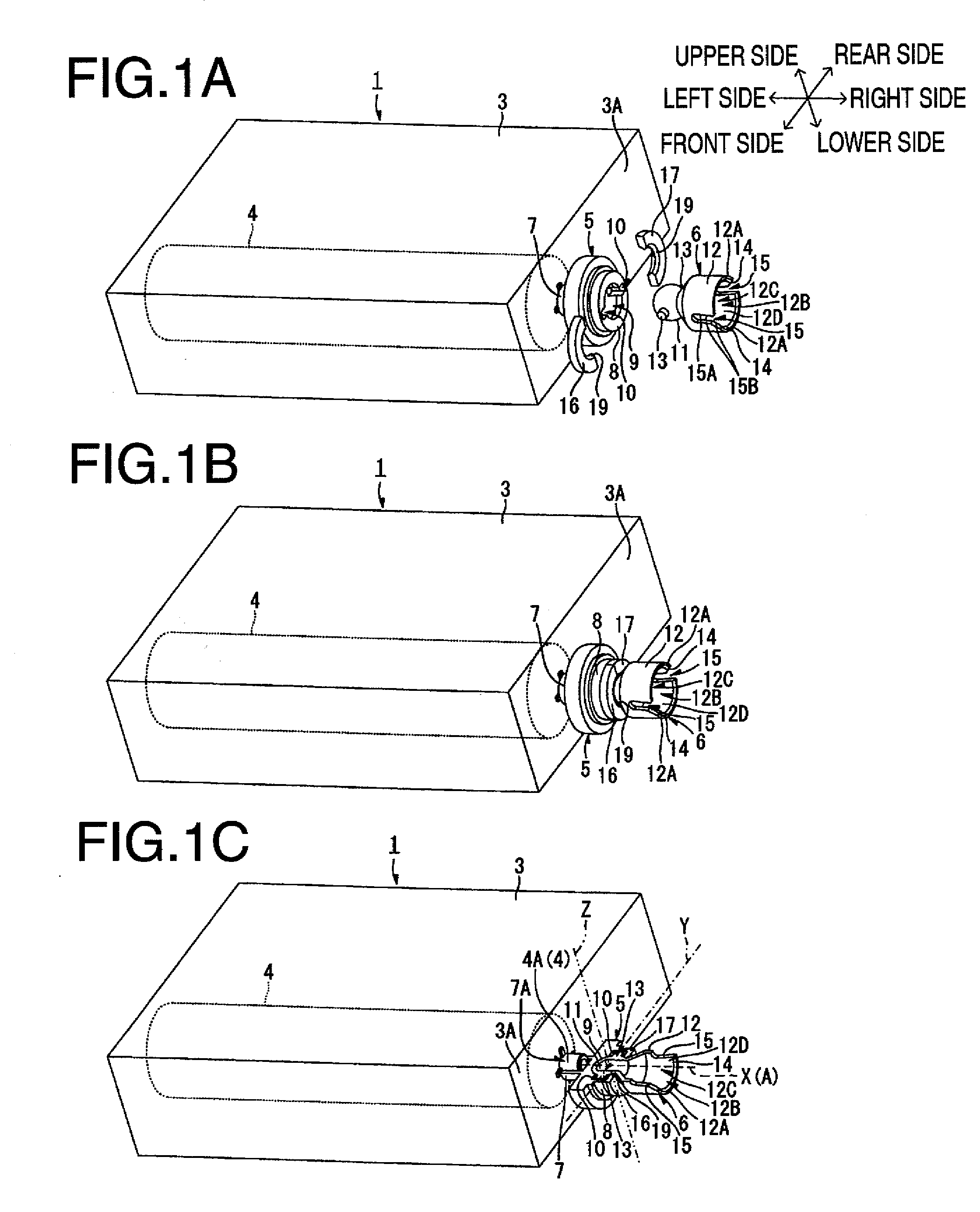
[0027]As shown in FIG. 2B, the cartridge 1 is configured to be detachably attachable to the device main body 2. Referring to FIG. 1B, the cartridge 1 includes a casing 3 which forms an outer appearance of the cartridge 1, a rotation body 4, a cartridge transmission unit 5, and a cartridge joint unit 6. The rotation body 4 is rotatably supported by the casing 3, and rotates when receiving a driving force from the device main body 2. The cartridge transmission unit 5 serves to transmit the driv...


PUM


Abstract

An image forming device comprising: a device main body; a cartridge detachably attachable to the device main body; a main body transmission unit to rotate about a first rotation axis; a main body joint unit to rotate about a second rotation axis allowed to intersect with the first rotation axis; a cartridge transmission unit configured to rotate about a third rotation axis and to transmit a driving force to a rotation body; and a cartridge joint unit configured to be able to rotate about a fourth rotation axis allowed to intersect with the third rotation axis, and configured to rotate coaxially with respect to the main body joint unit and to rotate the cartridge transmission unit when the main body transmission unit rotates in a state where the cartridge is attached to the device main body and the cartridge joint unit is coupled to the main body joint unit.

Description

CROSS-REFERENCE TO RELATED APPLICATION[0001]This application claims priority under 35 U.S.C. §119 from Japanese Patent Application No. 2009-208382, filed on Sep. 9, 2009. The entire subject matter of the application is incorporated herein by reference.BACKGROUND[0002]1. Technical Field[0003]Aspects of the present invention relate to an image forming device, such as a laser printer, and a cartridge attached to the image forming device.[0004]2. Related Art[0005]Image forming devices configured such that a process cartridge is detachably attachable to a main body casing of the image forming device have been widely used. For example, the process cartridge is configured to have a drum cartridge holding a photosensitive drum and a development cartridge holding a development roller. In this configuration, the development cartridge is detachably attachable to the drum cartridge.[0006]The development cartridge is provided with a driven gear for receiving a driving force from the main body ca...

Claims


Application Information

Patent Timeline
Patent Type & Authority Applications(United States)
IPC IPC(8): G03G15/00
CPCG03G21/186
Inventor OKABE, YASUSHI
Owner BROTHER KOGYO KK
Why Eureka
Try Eureka