Eureka AIR delivers breakthrough ideas for toughest innovation challenges, trusted by R&D personnel around the world.

Audio Jack Connector Device

Inactive Publication Date: 2011-03-10
PPC BROADBAND INC
View PDF83 Cites 24 Cited by
  • Summary
  • Abstract
  • Description
  • Claims
  • Application Information

AI Technical Summary

Benefits of technology

[0024]The audio jack connector device provides a shield for the center wire throughout the entire connector to prevent noise and interference from external or environmental conductors. Moreover, the shield prevents the signal from the center wire from radiating outside the connector. Additionally, the compactness of the connector allows closer spacing between audio jack connectors and offers more clearance between conventionally spaced sockets.

Problems solved by technology

Pre-made assemblies are of good to excellent build quality, but are not always convenient in length.
Either they are too long and create unnecessary loss in a studio set-up, or they are too short and not repairable in a live performance or road set-up.
Field installable connectors solve the needs of custom preparations and make it easier to repair a damaged end, but they require clumsy set-screw connections, which often become loose over time and require bulky connector bodies to house the components, or solder, which requires soldering gear, both which can be a nuisance to use.
Another problem with current connectors, factory installed or otherwise, is that the internal wire terminations are two non-coaxial individual terminals requiring non-coaxial break-out of the cable end, losing any shielding benefits of the cable conductors being coaxial.
Although such preassembled compressible connectors are known for use with F connectors, there are no suitable preassembled compressible phone plug connectors available on the market.
The metal band that is used to crimp the shield of the coaxial cable is a loose piece that could be easily dropped or lost.

Method used


Image

  • Audio Jack Connector Device
  • Audio Jack Connector Device
  • Audio Jack Connector Device

Examples


Embodiment Construction

[0037]Present invention: means at least some embodiments of the present invention; references to various feature(s) of the “present invention” throughout this document do not mean that all claimed embodiments or methods include the referenced feature(s).

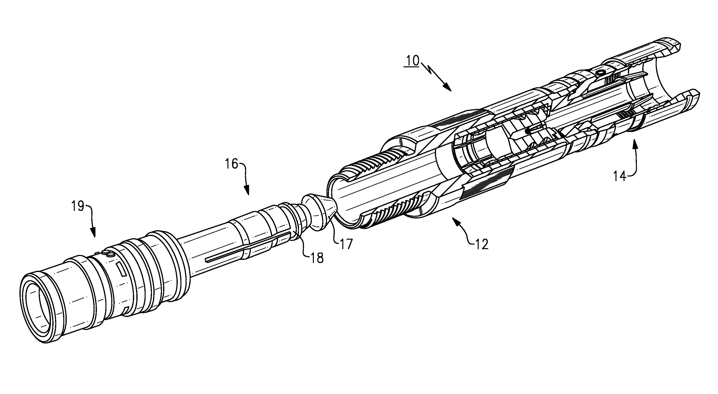
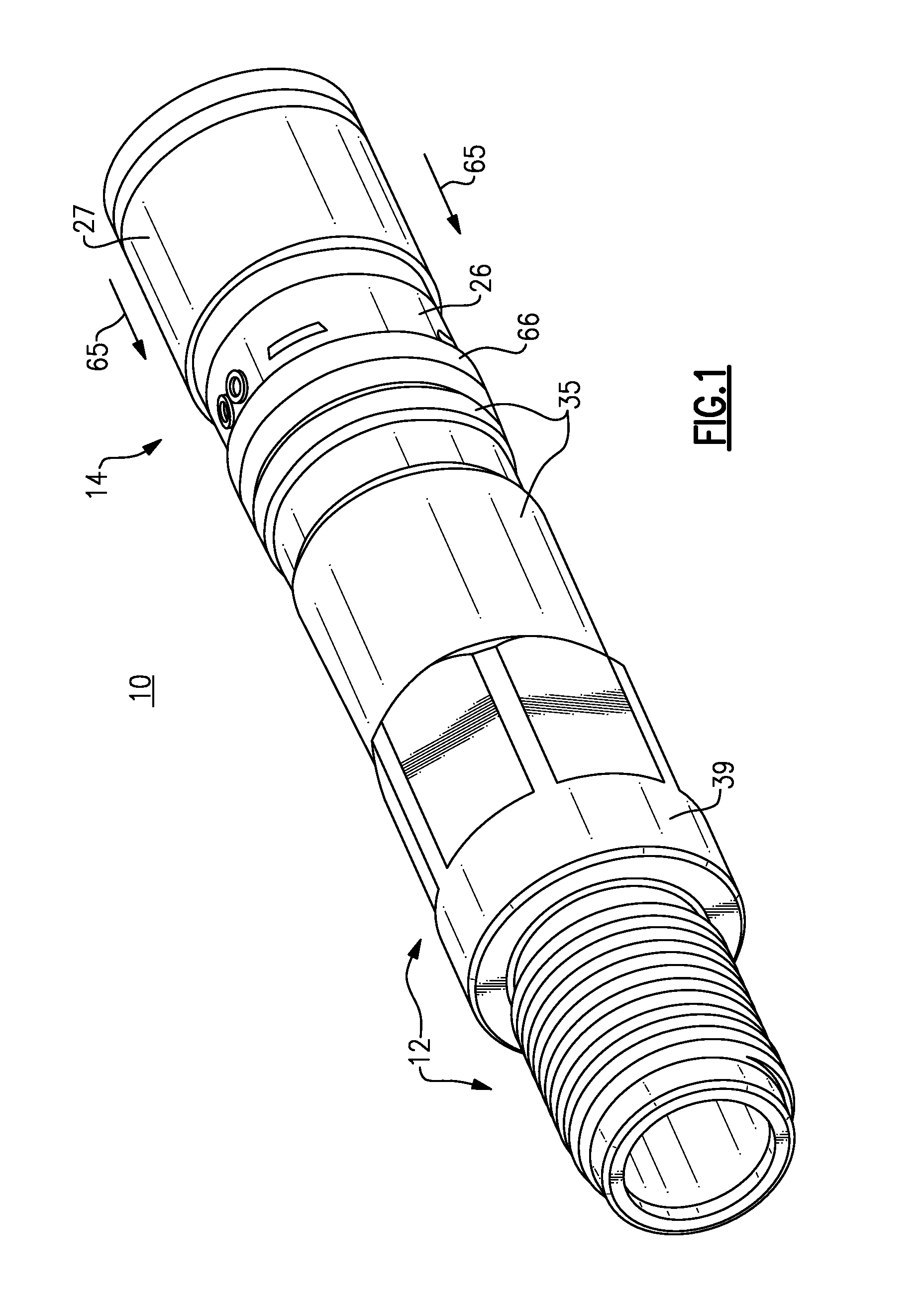
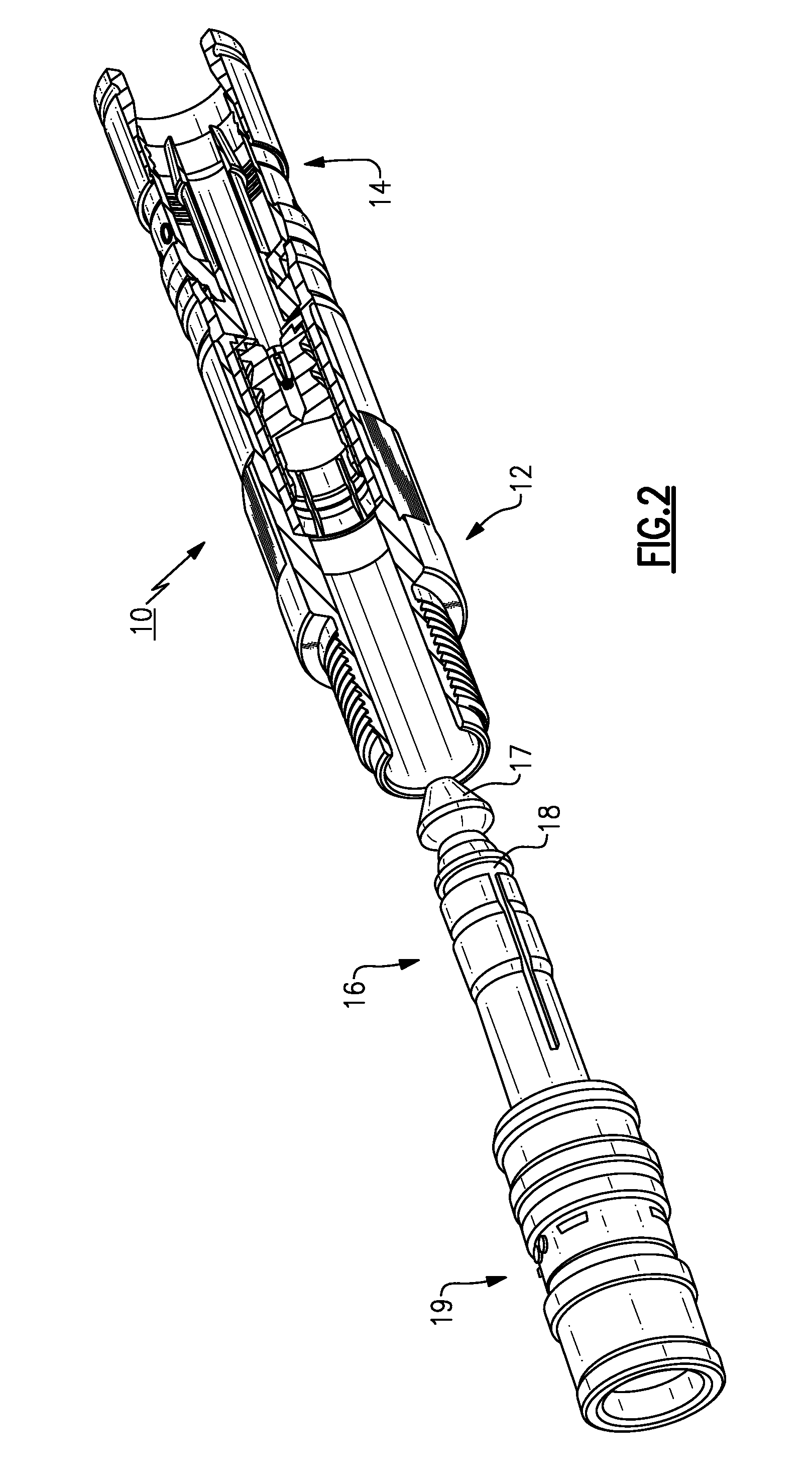
[0038]As will be appreciated, an embodiment of the present invention provides an audio jack connector device 10 as shown in FIGS. 1-7. Audio jack connector device 10 includes an audio jack 12 at one end and a connector 14 at the opposite end. Device 10 is preferably provided as a preassembled configuration to ease handling and installation during use.

[0039]Connector 10 connects an audio plug 16, shown in FIG. 2, having a tip 17 and a stem 18, to a coaxial cable (shown in FIG. 7) by insertion of audio plug 16 into audio jack 12. Audio plug 16 is also shown with a coaxial cable connector 19, which is the subject of commonly owned, copending application Ser. No. 12 / 540,683, filed Aug. 13, 2009, the contents of which are hereby incorpora...


PUM


Abstract

An audio jack connector device having an audio jack and a connector, the audio jack having a socket adapted to receive the tip end of the audio plug and the connector adapted to engage a cable, wherein the connector is adapted to mechanically and electrically connect by compression the coaxial cable to the audio jack.

Description

CROSS REFERENCE TO RELATED APPLICATIONS[0001]This application is related to U.S. patent application Ser. No. 12 / 540,683, filed Aug. 13, 2009, which is hereby incorporated by reference in its entirety.TECHNICAL FIELD[0002]Embodiments of the present invention relate generally to coaxial cable connectors, and more particularly to, audio jack compression connectors.BACKGROUND[0003]Currently, two-conductor tip-sleeve (TS) audio connectors, also known as audio plugs and phone plugs, are widely available as part of pre-made jumper assemblies and also as field installable connector / cable kits. Pre-made assemblies are of good to excellent build quality, but are not always convenient in length. Either they are too long and create unnecessary loss in a studio set-up, or they are too short and not repairable in a live performance or road set-up. Field installable connectors solve the needs of custom preparations and make it easier to repair a damaged end, but they require clumsy set-screw conne...

Claims


Application Information

Patent Timeline
IPC IPC(8): H01R9/05H01R24/04
CPCH01R9/05H01R2103/00H01R24/58H01R13/622
Inventor MONTENA, NOAH
Owner PPC BROADBAND INC
Why Eureka
Eureka Blog
Learn More