Phone Plug Connector Device

a technology of connector device and plug-in connector, which is applied in the direction of coupling device connection, manufacturing tools, metal working apparatus, etc., can solve the problems of unfavorable studio setup, unfavorable studio setup, and long length of pre-made assemblies, so as to prevent noise and interference, compact connector, and convenient spacing

a technology of connector device and plug-in connector, which is applied in the direction of coupling device connection, manufacturing tools, metal working apparatus, etc., can solve the problems of unfavorable studio setup, unfavorable studio setup, and long length of pre-made assemblies, so as to prevent noise and interference, compact connector, and convenient spacing

US20110039449A1Inactive Publication Date: 2011-02-17PPC BROADBAND INC

Image

  • Phone Plug Connector Device
  • Phone Plug Connector Device
  • Phone Plug Connector Device

Examples


Embodiment Construction

ā€œPresent inventionā€ means at least some embodiments of the present invention; references to various feature(s) of the ā€œpresent inventionā€ throughout this document do not mean that all claimed embodiments or methods include the referenced feature(s).

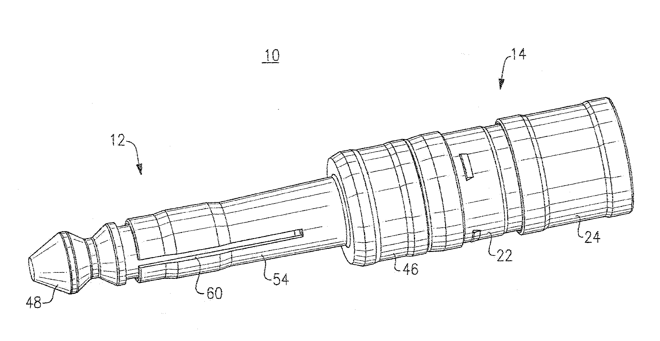
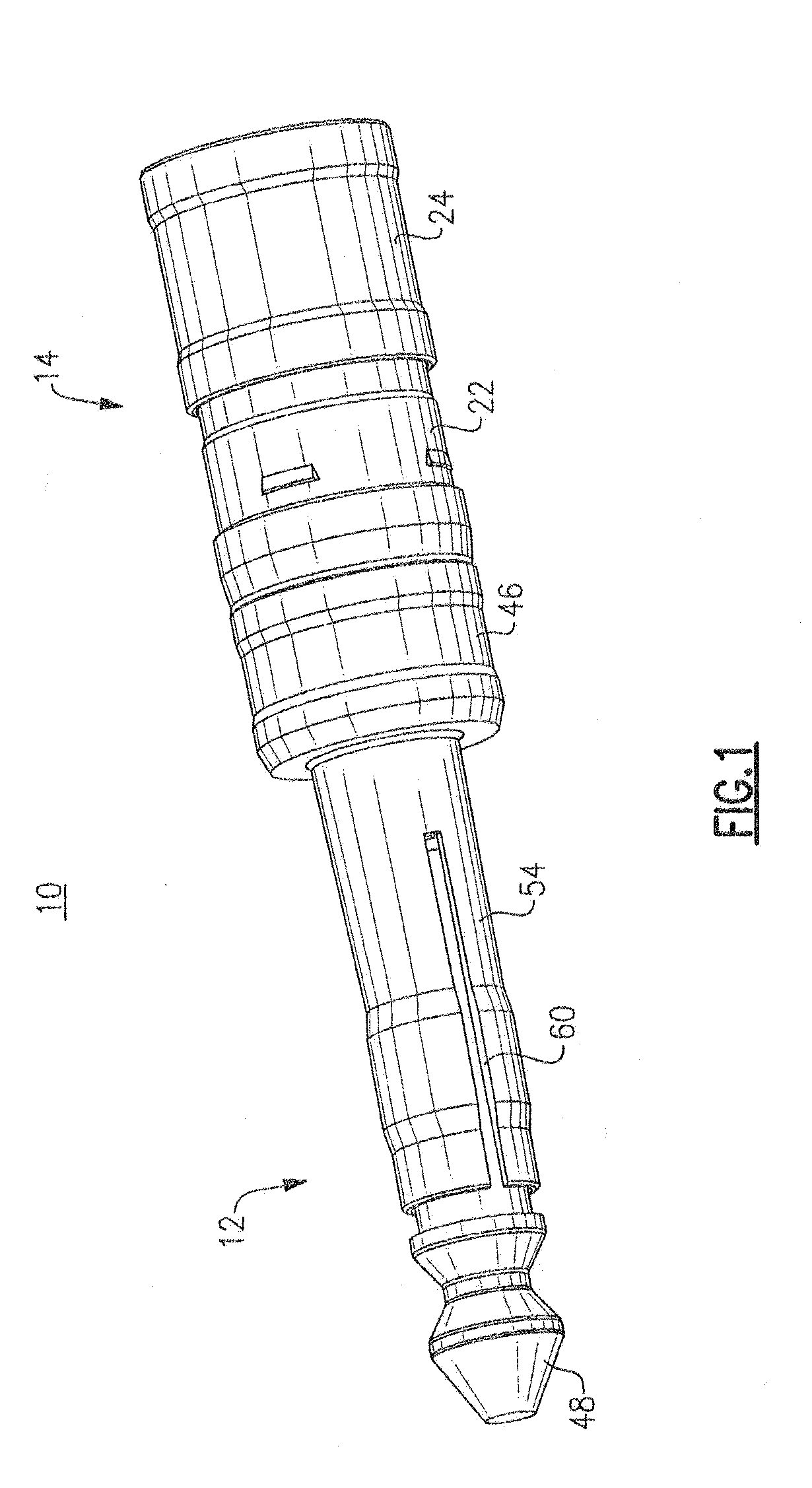
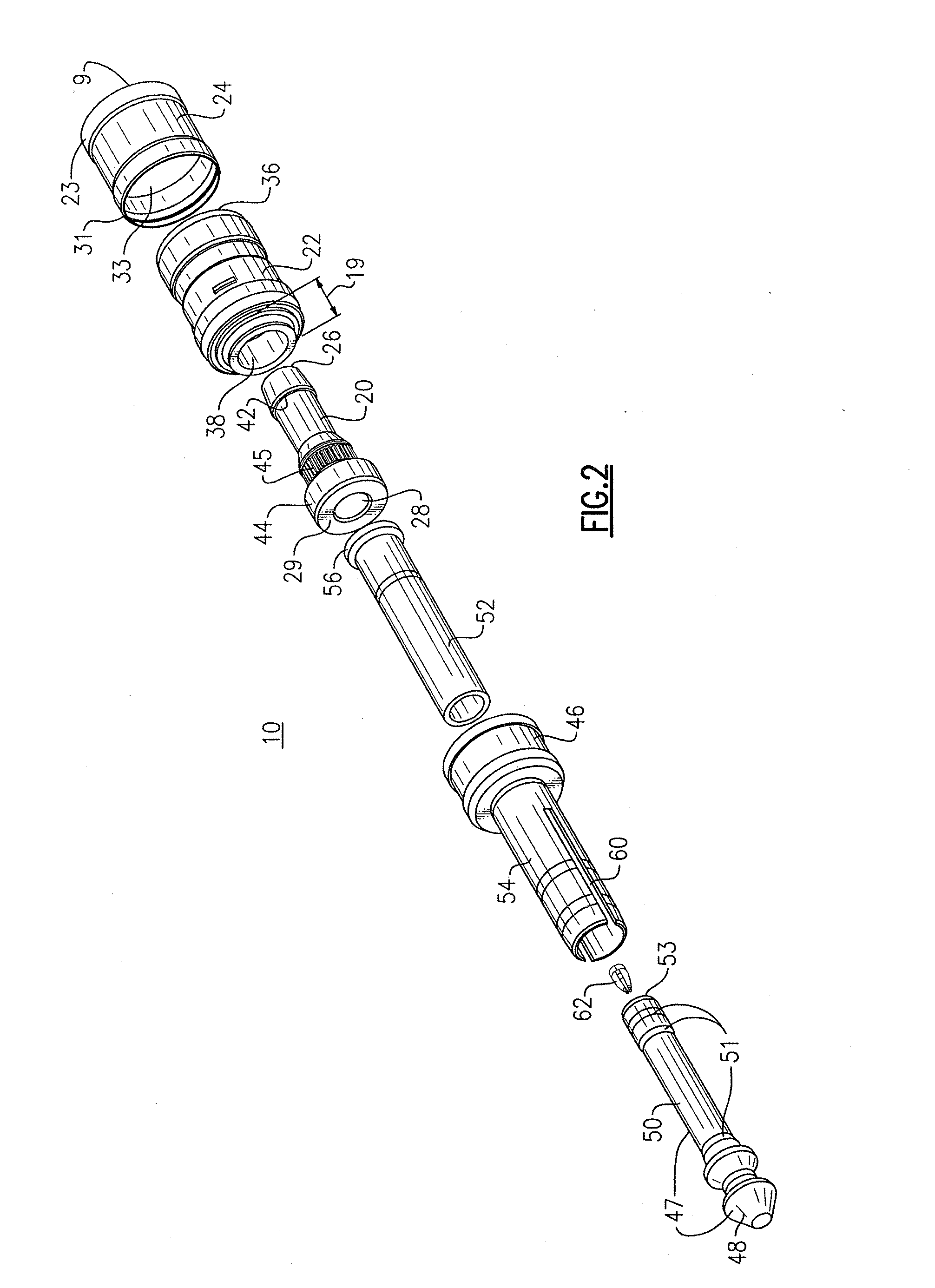
As will be appreciated, an embodiment of the present invention provides a phone plug connector device 10 as shown in FIG. 1. Phone plug connector device 10 includes a phone plug 12 and a connector 14. Device 10 is preferably provided as a preassembled configuration to ease handling and installation during use.

Connector 14 connects phone plug 12 to a coaxial cable by means of compression without the need for soldering, crimping or tooling of individual conductors. The coaxial cable can be a known type having an electrical center conductor surrounded by and spaced radially inwardly from a braid conductor or conductive sheath by a foil and an insulator core. A dielectric covering or sheathing jacket surrounds the braid and includes the outer...


PUM

PropertyMeasurementUnit
angleaaaaaaaaaa
angleaaaaaaaaaa
anglesaaaaaaaaaa

Abstract

A phone plug connector device having a preassembled phone plug and connector, wherein the phone plug includes a conductive tip and a stem, wherein the connector connects the phone plug to a coaxial cable, wherein the coaxial cable comprises a center conductor surrounded by a first dielectric, the first dielectric being surrounded by a first conductive sheath, and the first conductive sheath surrounded by a protective outer jacket, wherein the connector connects the coaxial cable to the phone plug mechanically and electrically by compression.

Description

TECHNICAL FIELDEmbodiments of the present invention relate generally to coaxial cable connectors, and more particularly to, compression connectors for use with phone plugs.BACKGROUNDCurrently, two-conductor tip-sleeve (TS) connectors, also known as phone plugs, are widely available as part of pre-made jumper assemblies and also as field installable connector / cable kits. Pre-made assemblies are of good to excellent build quality, but are not always convenient in length. Either they are too long and create unnecessary loss in a studio set-up, or they are too short and not repairable in a live performance or road set-up. Due to the long length of the head shell of the connector, the cable will be forced to have a tight bend radius, which can be inconvenient to use. Moreover, the diameter of the head shell tends to be too bulky creating clearance problems at the point of insertion of the plug into the panel. It may not be possible to fit plugs into consecutive or adjacent slots due to t...

Claims


Application Information

Patent Timeline
17 Feb 2011
Publication
US20110039449A1
IPC
H01R9/05; H01R43/042
CPC
H01R9/0524; H01R24/58; Y10T29/49208; H01R2201/16; Y10T29/53235; H01R2103/00
Inventors
MONTENA, NOAH