Data synchronizer system

Inactive Publication Date: 2006-09-07
PIXART IMAGING INC
View PDF8 Cites 4 Cited by
  • Summary
  • Abstract
  • Description
  • Claims
  • Application Information

AI Technical Summary

Benefits of technology

[0012] It is an advantage of the invention that the first and second switches divide the source pulse and data signals among synchronizers and first memory units so that these signals are more readily synchronized.
[0013] It is an advantage of the invention that pulses of the source signals can be more closely spaced with

Problems solved by technology

Such loss can be in the form of a pulse that is not sampled because its own clock and the sampling clock are too far out of phase.
However in real systems, this prob

Method used


Image

  • Data synchronizer system
  • Data synchronizer system
  • Data synchronizer system

Examples


Embodiment Construction

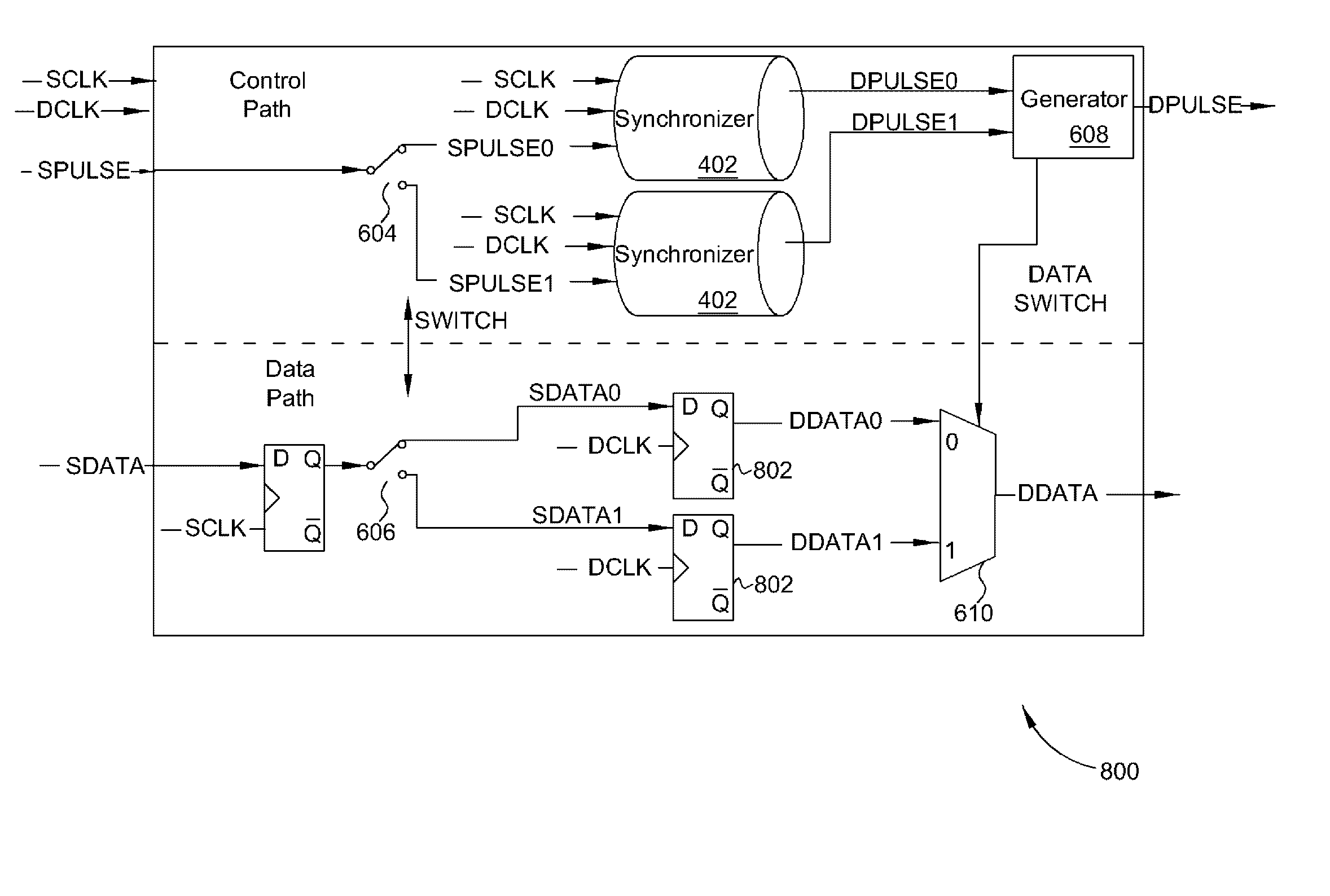
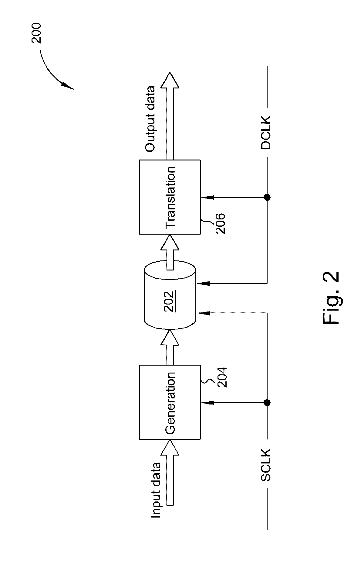
[0026] Please refer for FIG. 2 which illustrates a block diagram of a data synchronizer system 200 according to the invention. The data synchronizer system 200 includes a piped synchronizer 202, a generation circuit 204, and a translation circuit 206. The piped synchronizer 202 includes a plurality of synchronizers each for handling a part of data input into the data synchronizer system 200. The generation circuit 204 sends a part of the input data to a synchronizer of the piped synchronizer 202, and the translation circuit 206 assembles the output of the piped synchronizer 202 into the expected output data. Generally, the generation circuit 204 operates according to a source clock SCLK, the translation circuit operates according to a destination clock DCLK (the clocks SCLK and DCLK defining two clock domains), and the piped synchronizer 202 operates according to both clocks SCLK, DCLK.

[0027] Please refer to FIG. 3 which illustrates one embodiment of the piped synchronizer 202 acco...


PUM


Abstract

A data synchronizer system includes at least two synchronizers for receiving a source pulse signal, a corresponding source clock, and a destination clock. At least two first memory units each have a destination clock input. A first switch has an input coupled to the source pulse signal and an output selectively coupled to a source pulse signal input of any one of the synchronizers. A second memory unit has an input coupled to the source data signal and a clock input coupled to the source clock. A second switch has an input coupled to an output of the second memory unit and an output selectively coupled to an input of any one of the first memory units. A generator is coupled to outputs of the synchronizers for outputting a data switch signal. A multiplexer has inputs coupled to outputs of the first memory units and outputs a destination data signal.

Description

BACKGROUND OF INVENTION [0001] 1. Field of the Invention [0002] The present invention relates to digital electronics, and more specifically, to data synchronizers. [0003] 2. Description of the Prior Art [0004] Synchronizers are typically used to reduce information loss in systems having more than one clock. Such loss can be in the form of a pulse that is not sampled because its own clock and the sampling clock are too far out of phase. In ideal systems this does not happen since clocks are assumed to have periods that are perfect integer multiples of each other and that are precisely in phase. However in real systems, this problem can occur because clock signals can easily become uncorrelated or skewed by a multitude of reasons including circuit delays, conductor lengths, and interference. [0005] The conventional synchronizer takes as input a source pulse signal and source and destination clock signals that may be out of phase and may have a non-integer relationship of periods. Such...

Claims


Application Information

Patent Timeline
IPC IPC(8): H04L7/00
CPCH04L7/0012H04L7/0037
Inventor HSU, HUNG-YUANCHUNG, CHING-LIN
Owner PIXART IMAGING INC
Why Eureka
Try Eureka