Method, system, and bus coupler for exchanging data between a higher-level network and a lower-level network

a technology of data exchange and bus coupler, applied in the field of automatic technology, can solve the problems of unnecessarily high cost, large data overhead of ethernet data frame, and carried along without any benefit to the lower-level bus system, and achieve the effect of accurate error location in communication, rapid error recognition, and rapid respons

Active Publication Date: 2011-03-10
PHOENIX CONTACT GMBH & CO KG
View PDF2 Cites 19 Cited by
  • Summary
  • Abstract
  • Description
  • Claims
  • Application Information

AI Technical Summary

Benefits of technology

[0006]The object of the invention is to provide a bus coupler, a communication system, and a method for exchanging data between an external network and a lower-level bus system via a bus coupler, by means of which decentralized and autonomous monitoring of the lower-level bus system is possible without limiting the transmission bandwidth, and in particular also during normal operation, i.e., during the transmission of payload data. In addition, rapid error recognition, and if necessary a rapid response to recognized errors as well as accurate error location in the communication between two bus users, is made possible.

Problems solved by technology

However, an Ethernet data frame has a considerable overhead of data, which are needed primarily for controlling Ethernet telegrams via an Ethernet-based network.
Another disadvantage of an Ethernet-based field bus system is that each bus user must be physically equipped with an Ethernet interface, even though in many cases it is necessary to span only small distances.
This results in unnecessarily high costs.
However, a disadvantage of the method described in EP 1 590 927 B1 is that the Ethernet telegram circulating on the ring-shaped transmission path contains the above-described overhead of data, which is carried along without any benefit to the lower-level bus system.
Transmission bandwidth of the lower-level bus system is thus unnecessarily wasted without the ability to implement management and / or control tasks for the lower-level bus system.
In addition, use of the ring-shaped transmission path results in “jitter,” which limits the maintenance of real-time requirements.

Method used


Image

  • Method, system, and bus coupler for exchanging data between a higher-level network and a lower-level network
  • Method, system, and bus coupler for exchanging data between a higher-level network and a lower-level network
  • Method, system, and bus coupler for exchanging data between a higher-level network and a lower-level network

Examples


Embodiment Construction

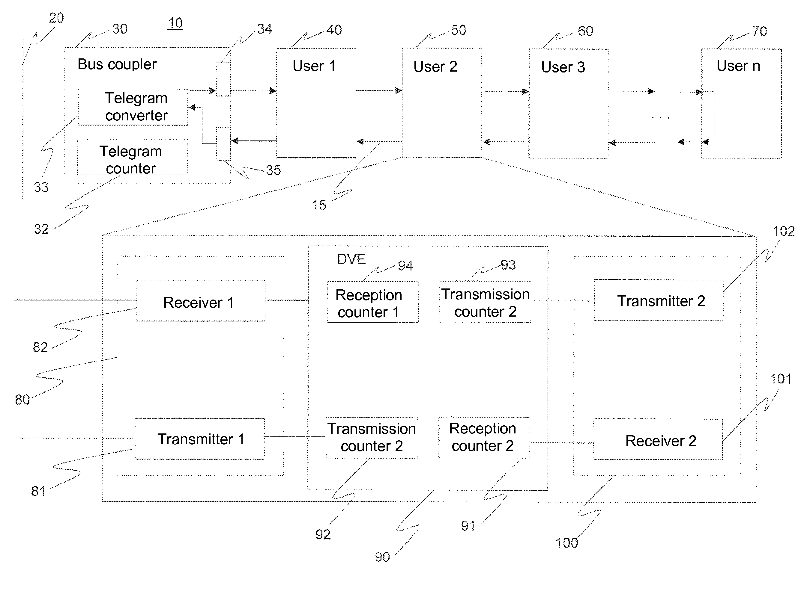
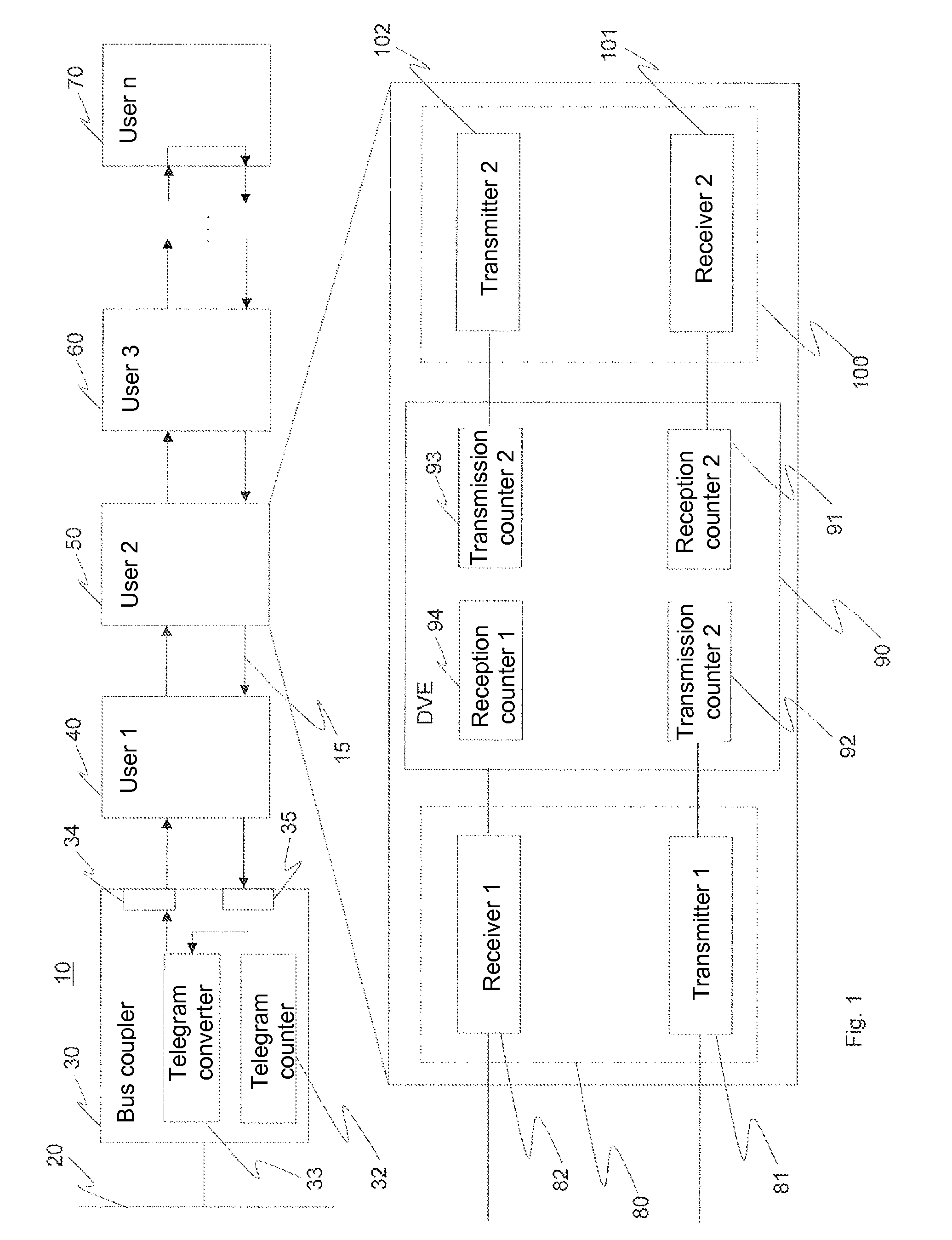
[0049]FIG. 1 shows an example of a communication system 10, which may be an automated system. The automated system 10 has a higher-level, i.e., external, network 20 which in the present example is an Ethernet-based network. Ethernet telegrams may be transmitted via the external network 20. A structure of an Ethernet telegram 170, known per se, is illustrated in FIG. 3a. The higher-level network 20 is connected to a lower-level, i.e., internal, bus system 15 via a bus coupler30. In the present example the internal bus system 15 includes a ring-shaped transmission path. The bus coupler 30 has an interface (not illustrated) to which the external network 20 is connected. The bus coupler also has an internal interface which contains a transmitter unit 34 and a receiver unit 35, to which a bus user 40 of the bus system 15 is connected. The lower-level bus system 15 includes, for example, n bus users 40 through 70 connected in series.

[0050]In addition, a telegram converter device 33 is imp...


PUM


Abstract

The invention relates to a bus coupler which converts a network-specific telegram arriving from an external network to an internal data telegram which transmits only the payload data from the network-specific telegram. The internal data telegram also contains at least one state information field for internal control information. The internal data telegram is transferred from the bus coupler to an internal bus system to which multiple bus users are connected in series. Each bus user connected to the internal bus system is able to monitor, in a decentralized and preferably autonomous manner, the communication quality of the lower-level bus system, and to initiate actions, depending on the implementation, on the basis of the internal control information received from the bus coupler, the internal control information generated by the particular bus user, and / or the internal control information received from the directly adjacent bus users.

Description

FIELD OF THE INVENTION[0001]The invention relates in general to automation technology, and in particular to a method, a bus coupler, and a communication system for real-time control of a lower-level bus system.BACKGROUND OF THE INVENTION[0002]Ethernet-based field bus systems are being increasingly used in automation technology. Based on the Ethernet protocol, these systems use an Ethernet data frame to access a connected device. However, an Ethernet data frame has a considerable overhead of data, which are needed primarily for controlling Ethernet telegrams via an Ethernet-based network.[0003]Another disadvantage of an Ethernet-based field bus system is that each bus user must be physically equipped with an Ethernet interface, even though in many cases it is necessary to span only small distances. This results in unnecessarily high costs.[0004]For carrying out control tasks in real time, it is known from EP 1 590 927 B1 to connect the bus user provided for the real-time application ...

Claims


Application Information

Patent Timeline
Patent Type & Authority Applications(United States)
IPC IPC(8): G06F13/42G06F13/00
CPCG05B19/042G05B2219/25012G05B2219/25174H04L12/24H04L2012/4026H04L12/4625H04L41/00H04L2012/40221H04L12/40006
Inventor KUSCHKE, DETLEVHOFFMANN, MICHAELWEISS, DOMINIK
Owner PHOENIX CONTACT GMBH & CO KG
Why Eureka
Try Eureka