Signal processing method of magnetic recording medium and magnetic record reproduction apparatus

a technology of magnetic recording medium and recording apparatus, which is applied in the field of signal processing method of magnetic recording medium and magnetic record reproduction apparatus, can solve the problems of difficult to completely prevent the generation of sub-pulses, incorrect recognition of sub-pulses as reproduced signals, and error in signal reproduction, so as to reduce blur, reduce the influence of blur, and increase the recording area of magnetic bits in each track

Inactive Publication Date: 2006-03-23
FUJIFILM CORP +1
View PDF8 Cites 0 Cited by
  • Summary
  • Abstract
  • Description
  • Claims
  • Application Information

AI Technical Summary

Benefits of technology

[0025] Further, if a magnetic recording medium on which burst signals for amplitude servo tracking are recorded so that the ends of the burst signals with respect to the width direction of the track, which are adjacent to each other with respect to the direction of the track, overlap with each other, recording areas of the magnetic bits in each track can be increased. Further, even if recorded information is blurred, or demagnetization of record or the like occurs at an end of a recording area of each bit with respect to the width direction of the track, it is possible to reduce the influence from the blur, demagnetization of record, or the like. Hence, it is possible to prevent a drop in the accuracy of position servo tracking.
[0026] Further, a magnetic recording medium onto wh

Problems solved by technology

However, the magnetic transfer method has a technical problem that when signals are transferred onto the magnetic recording medium from the master information carrier, an unclear magnetic recording area (reversely magnetized area) is produced on the magnetic recording medium.
Therefore, there is a possibility that the sub-pulse is recognized as a reproduced signal by a magnetic reproduction apparatus, which may cause an error in reproduction of the signals.
When transferred signals are, for example, servo sig

Method used


Image

  • Signal processing method of magnetic recording medium and magnetic record reproduction apparatus
  • Signal processing method of magnetic recording medium and magnetic record reproduction apparatus
  • Signal processing method of magnetic recording medium and magnetic record reproduction apparatus

Examples


Embodiment Construction

[0040] Hereinafter, an embodiment of the present invention will be described with reference to attached drawings. In this embodiment, amplitude servo signals are recorded on a magnetic recording medium.

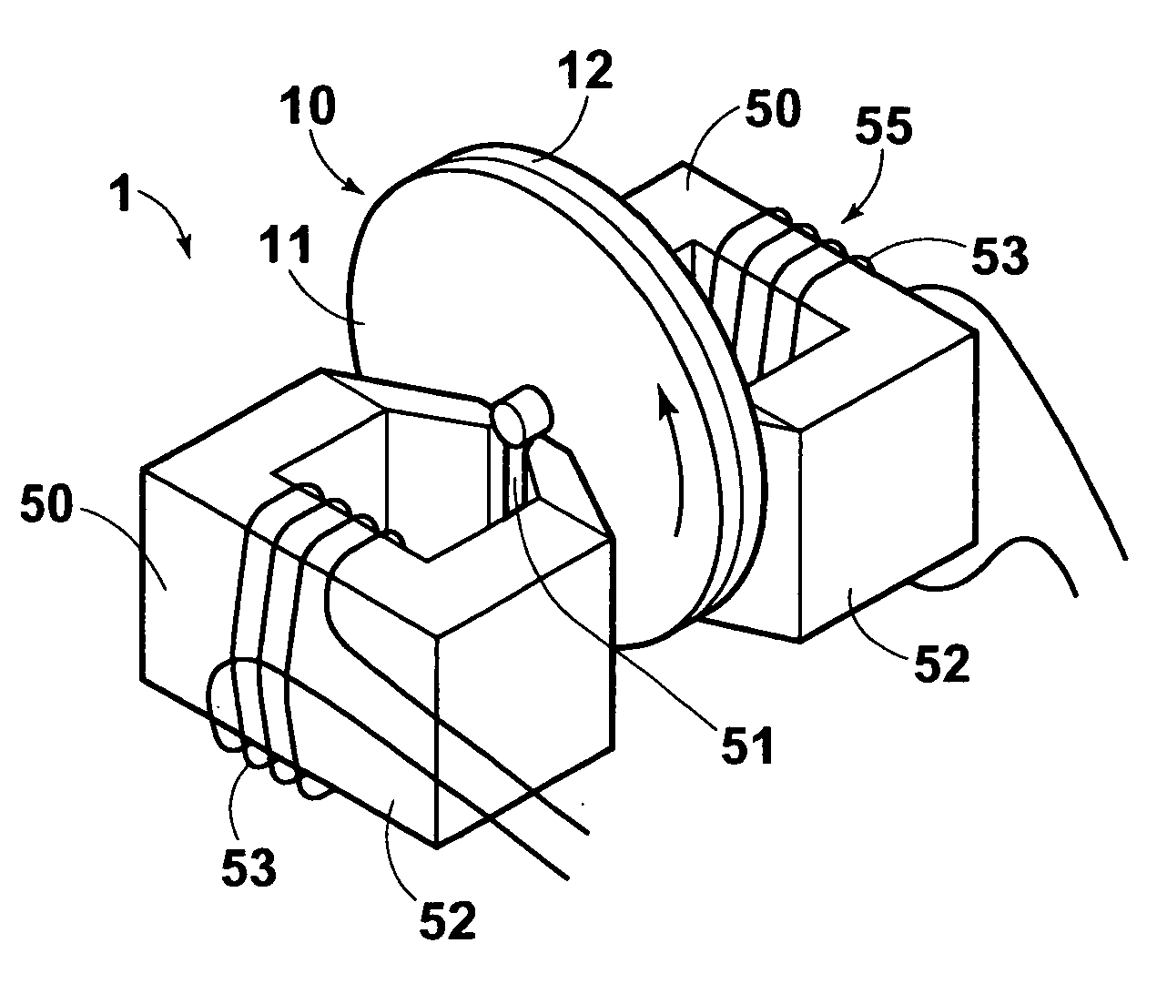
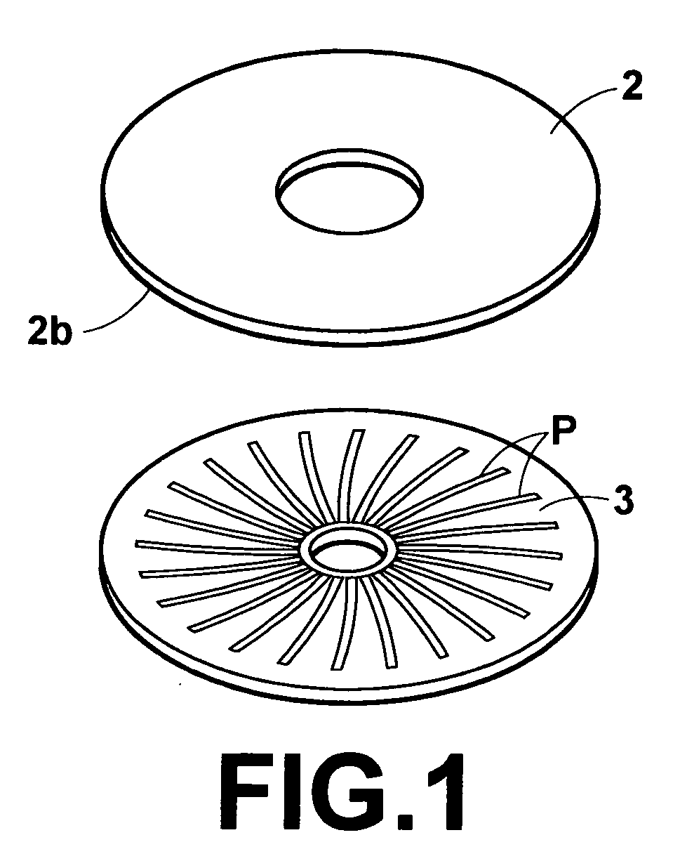
[0041]FIG. 1 is a perspective view illustrating a magnetic recording medium 2 which is used in a signal processing method according to the present invention and a master information carrier 3 for magnetic transfer, from which signals are magnetically transferred onto the magnetic recording medium 2 to be recorded thereon. The magnetic recording medium 2 is, for example, a disk-shaped magnetic recording medium such as a hard disk or flexible disk, on which a magnetic recording layer or layers are formed on one side or both sides thereof. In this embodiment, a magnetic recording medium 2 which has a recording surface 2b on one side of a disk-shaped substrate 21 thereof is illustrated. An in-plane magnetic recording layer 22 is formed in the magnetic recording medium 2 (please refer to ...


PUM


Abstract

When signals are read out by a magnetic head from a magnetic recording medium on which magnetic bits corresponding to information are recorded along the tracks thereof by a magnetic transfer method, if a space which is longer than or equal to a length corresponding to three bits is present between consecutive magnetic bits, readout of signals from a sub-pulse generation area in the space is cancelled in readout of the magnetic bits by the magnetic head along the tracks. The signals are not read out at all, or even if the signals are read out, they are not processed as valid signals.

Description

BACKGROUND OF THE INVENTION [0001] 1. Field of the Invention [0002] The present invention relates to a signal processing method in readout of signals from a magnetic recording medium, on which magnetic bits are recorded along the tracks thereof by using a magnetic transfer method. The present invention also relates to a magnetic record reproduction apparatus. [0003] 2. Description of the Related Art [0004] Conventionally, a magnetic transfer method for transferring magnetized patterns corresponding to information carried by a master information carrier for magnetic transfer onto a magnetic recording medium (slave medium) is well known. In this method, the master information carrier for magnetic transfer, which carries the information to be transferred, represented by very fine uneven patterns, and the magnetic recording medium are placed in close contact with each other, and a magnetic field for transfer is applied to the master information carrier for magnetic transfer and the magn...

Claims


Application Information

Patent Timeline
IPC IPC(8): G11B5/86G11B20/10G11B21/02
CPCG11B5/00G11B5/865G11B5/59688G11B5/09
Inventor NAGAO, MAKOTOYASUNAGA, TADASHI
Owner FUJIFILM CORP
Why Eureka
Try Eureka