Rotary control knob apparatus

Inactive Publication Date: 2011-03-17
DELPHI TECH INC
View PDF8 Cites 24 Cited by
  • Summary
  • Abstract
  • Description
  • Claims
  • Application Information

AI Technical Summary

Benefits of technology

[0003]The present invention provides an improved rotary control knob apparatus including a stationary knob retainer having a cylindrical post and an annular knob that slides over the retainer post, where the exterior periphery of the retainer post has a distributed array of compliant protrusions that contact the inner periphery of the knob to provide a resilient sliding interference fit between the knob and the retainer post. In a preferred arrangement, the retainer is secured against the rear surface of a control panel trimplate, and the knob is axially captured between the trimplate and a retainer flange extending radially outward from the base of the cylindrical post.

Problems solved by technology

Since this tilting or wobbling is aesthetically unpleasing, and can reflect unfavorably on the quality of the product, what is needed is a rotary control knob assembly in which the axial orientation of the knob is tightly controlled even though the parts of the assembly are subject to the usual manufacturing tolerance variations.

Method used


Image

  • Rotary control knob apparatus
  • Rotary control knob apparatus
  • Rotary control knob apparatus

Examples


Embodiment Construction

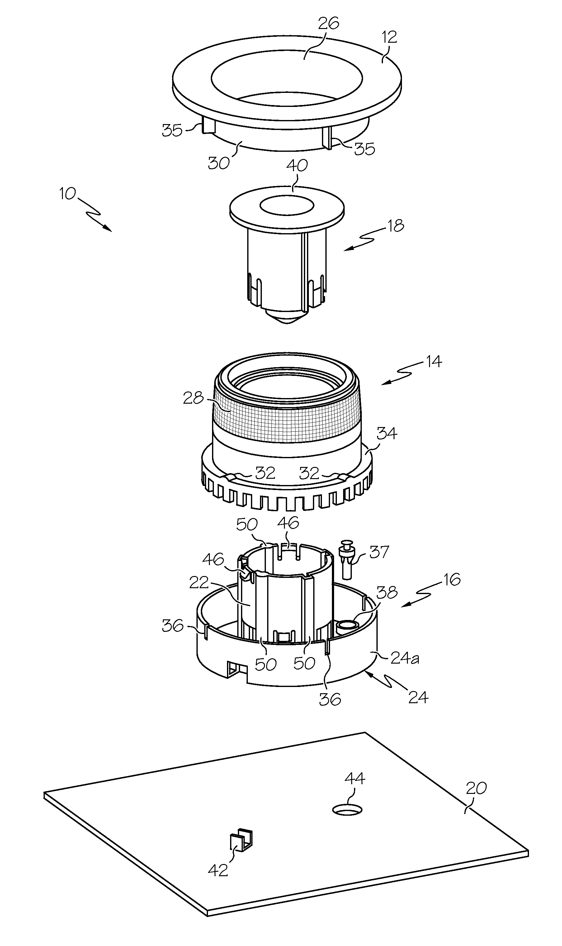
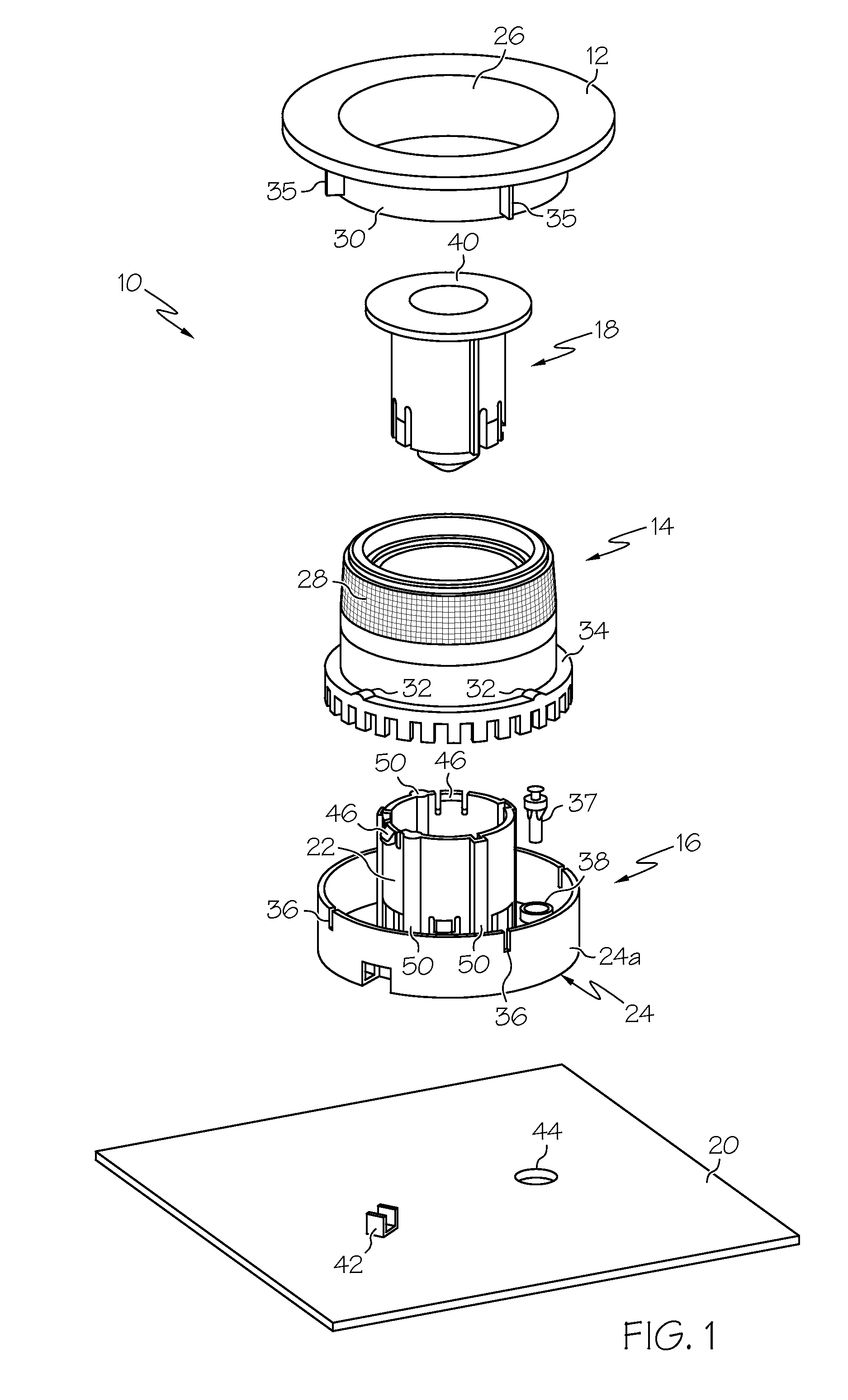
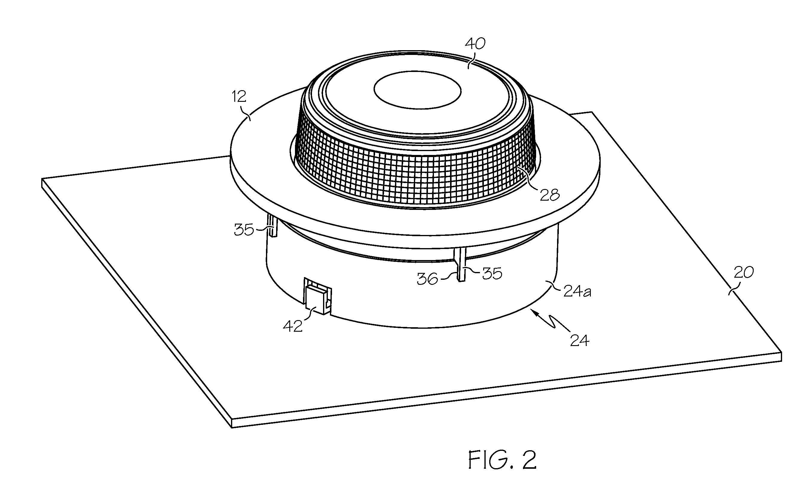
[0008]Referring to the drawings, and particularly to FIGS. 1-2, the reference numeral 10 generally designates a rotary control knob assembly mounted with respect to a trimplate 12 of an electronic product such as an automotive radio. The assembly 10 includes an annular control knob 14, a knob retainer 16, a push-button actuator 18, and a circuit board 20. The knob retainer 16 is preferably an injection-molded plastic part; it includes a hollow cylindrical post 22 and a cup-shaped flange 24 that extends radially outward from the base of the post 22. The push-button actuator 18 slides into the hollow retainer post 22, whereas the knob 14 slides over the retainer post 22 and is compliantly supported within the cup-shaped retainer flange 24. The trimplate 12 is provided with an opening 26 through which the grip portion 28 of knob 14 extends, and an inwardly depending cylindrical flange 30 that engages a set of radial ridges 32 formed on a toothed flange 34 of knob 14 to capture knob 14 ...


PUM


Abstract

A rotary control knob apparatus includes a stationary knob retainer having a cylindrical post and an annular knob that slides over the retainer post, where the exterior periphery of the retainer post has a distributed array of compliant protrusions that contact the inner periphery of the knob to provide a resilient sliding interference fit between the knob and the retainer post. In a preferred arrangement, the retainer is secured against the rear surface of a control panel trimplate, and the knob is axially captured between the trimplate and a retainer flange extending radially outward from the base of the cylindrical post.

Description

TECHNICAL FIELD[0001]The present invention relates to rotary control knobs for automotive and consumer electronics applications, and more particularly to an improved rotary control knob apparatus that minimizes axial tilting of the knob.BACKGROUND OF THE INVENTION[0002]Rotary knobs are commonly used in connection with automotive or consumer electronic products such as radios for user-adjustment of control parameters such as volume and tuning. A typical knob assembly comprises several mechanically coupled parts, and tolerance variations in the manufacture of the constituent parts can result in tolerance stack-up that allows the knob to axially tilt, or wobble, with respect to its mounting surface. Since this tilting or wobbling is aesthetically unpleasing, and can reflect unfavorably on the quality of the product, what is needed is a rotary control knob assembly in which the axial orientation of the knob is tightly controlled even though the parts of the assembly are subject to the u...

Claims


Application Information

Patent Timeline
Patent Type & Authority Applications(United States)
IPC IPC(8): G05G1/10
CPCY10T74/2084G05G1/12
Inventor BULIN, DAVID S.GILL, MARK A.CLUTE, DAVID J.NETHERTON, STEVEN V.
Owner DELPHI TECH INC
Why Eureka
Try Eureka