Circuit for driving an infrared transmitter LED with temperature compensation

a technology of infrared transmitter and circuit, which is applied in the direction of electromagnetic transmission, transmission, electric variable regulation, etc., can solve the problems of high temperature-dependent electro-optical properties, and achieve the effect of eliminating the resistor divider curren

Active Publication Date: 2011-03-17
DIALOG SEMICONDUCTOR GMBH
View PDF14 Cites 31 Cited by
  • Summary
  • Abstract
  • Description
  • Claims
  • Application Information

AI Technical Summary

Benefits of technology

[0015]A further object of the invention is to use a correction to t...

Problems solved by technology

However, the transmitter (infrared LED, for instance) and the receiver being used (phototransistor, for instance) are highly temperature-dependent in their electro-optical properties.
Without suitable temperature compensation, temperature fluctuations would be int...

Method used


Image

  • Circuit for driving an infrared transmitter LED with temperature compensation
  • Circuit for driving an infrared transmitter LED with temperature compensation
  • Circuit for driving an infrared transmitter LED with temperature compensation

Examples


Embodiment Construction

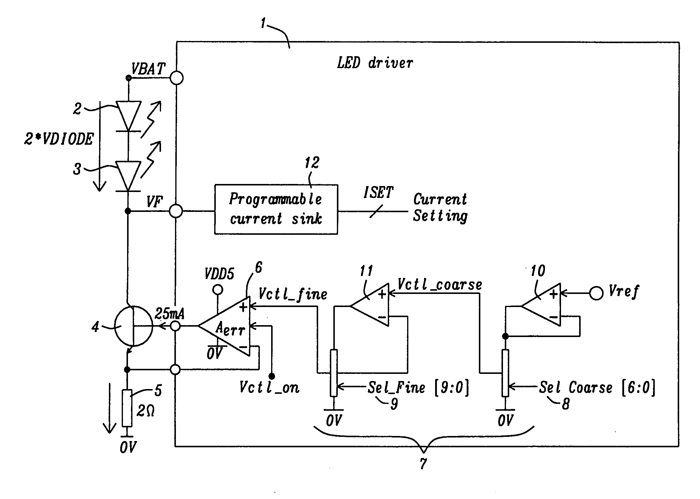
[0029]Systems and methods for circuits for driving infrared LEDs with a constant current with temperature compensation are disclosed. A preferred embodiment of the invention is part of a rain sensing system but the invention could be applied to a number of other applications as well especially for all applications requiring to maintain a constant light efficiency of the LEDs. An on-chip Digital Signal Processor (DSP) controls the operation in order to compensate the temperature dependency of the transmitter LED.

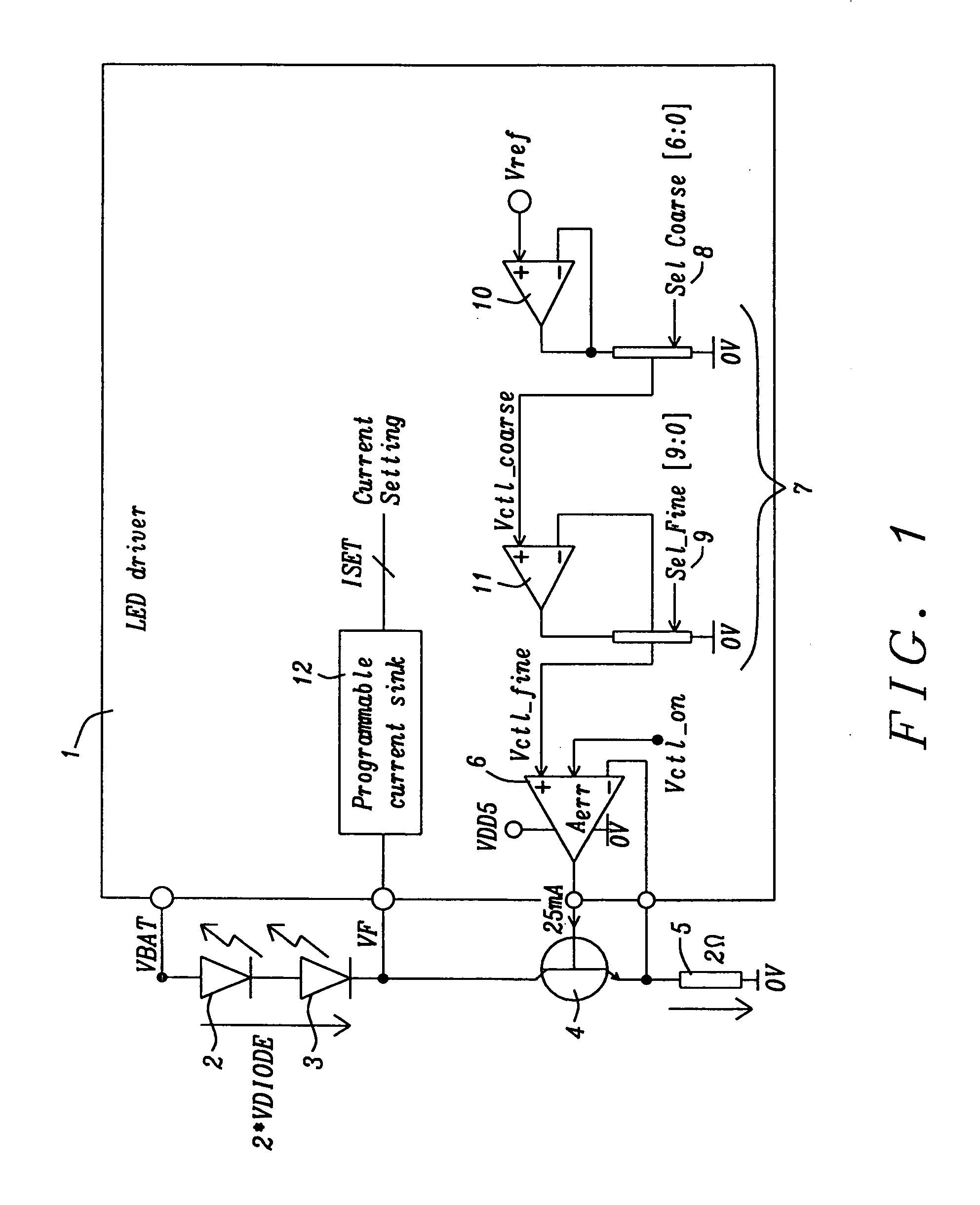
[0030]FIG. 1 illustrates a schematic for a preferred embodiment of a LED transmitter drive circuitry. FIG. 1 shows a LED driver circuit 1 of the present invention, two infrared transmitter diodes 2 and 3, an external n-p-n bipolar transistor 4, and an external resistor 5. Using two transmitter diodes is a non-limiting example, it is possible to use only one or more than two transmitter diodes with the present invention as well. a N-th diode in series generates a N×ΔVDIODE(T) ...


PUM


Abstract

Systems and methods to achieve a circuit for driving one or more infrared transmitter LEDs with temperature compensation have been disclosed. In a preferred embodiment of the invention the circuit has been applied for a rain sensing system. The junction temperature of the LED is measured and compensated by adjusting the driver current of a voltage-to-current converter driving the LED. The LED junction temperature is measured by comparing the difference in the forward diode voltage at different current densities. This voltage difference is extracted when switching the drive currents between different constant values. The measurement results are converted to digital values, which are used by a buffered dual ladder resistive DAC structure to adjust the drive current to temperature variations.

Description

BACKGROUND OF THE INVENTION[0001](1) Field of the Invention[0002]This invention relates generally to infrared transmitter light-emitting diodes (LEDs) and relates more specifically to a circuit driving infrared transmitter LEDs with temperature compensation.[0003](2) Description of the Prior Art[0004]The usage of infrared transmitter and receivers is getting more and more popular and is known for numerous different applications and includes a transmitter (such as an infrared light emitting diode (LED)), which transmits light in the infrared range, and an optical receiver (phototransistor or photodiode or photoresistor), which converts the optical infrared signal into a proportional electrical signal. However, the transmitter (infrared LED, for instance) and the receiver being used (phototransistor, for instance) are highly temperature-dependent in their electro-optical properties. Without suitable temperature compensation, temperature fluctuations would be interpreted as fluctuation...

Claims


Application Information

Patent Timeline
IPC IPC(8): H05B37/02H04B10/50H05B44/00
CPCH05B33/0854H04B10/502H05B45/18
Inventor JI, CANG
Owner DIALOG SEMICONDUCTOR GMBH
Why Eureka
Try Eureka