Image processing device, image processing method, and imaging device

a technology of image processing and image data, applied in image data processing, instruments, television systems, etc., can solve problems such as false colors, uneven pixel signals, etc., and achieve the effect of suppressing the degradation of perceived resolution and suppressing the increase of circuit scal

Inactive Publication Date: 2011-03-17
SANYO ELECTRIC CO LTD
View PDF16 Cites 27 Cited by
  • Summary
  • Abstract
  • Description
  • Claims
  • Application Information

AI Technical Summary

Problems solved by technology

A problem here is that, while the pixel intervals on the image sensor are even in both the horizontal and vertical directions, performing binned or skipped reading causes pixel signals to be present at uneven intervals.
If an image having such unevenly arrayed pixel signals is displayed unprocessed, jaggies and false colors result.

Method used


Image

  • Image processing device, image processing method, and imaging device
  • Image processing device, image processing method, and imaging device
  • Image processing device, image processing method, and imaging device

Examples


embodiment 1

[0177]First, a first embodiment (Embodiment 1) of the invention will be described. Unless otherwise indicated, numbered practical examples mentioned in the course of the following description of Embodiment 1 are those of Embodiment 1.

Example 1

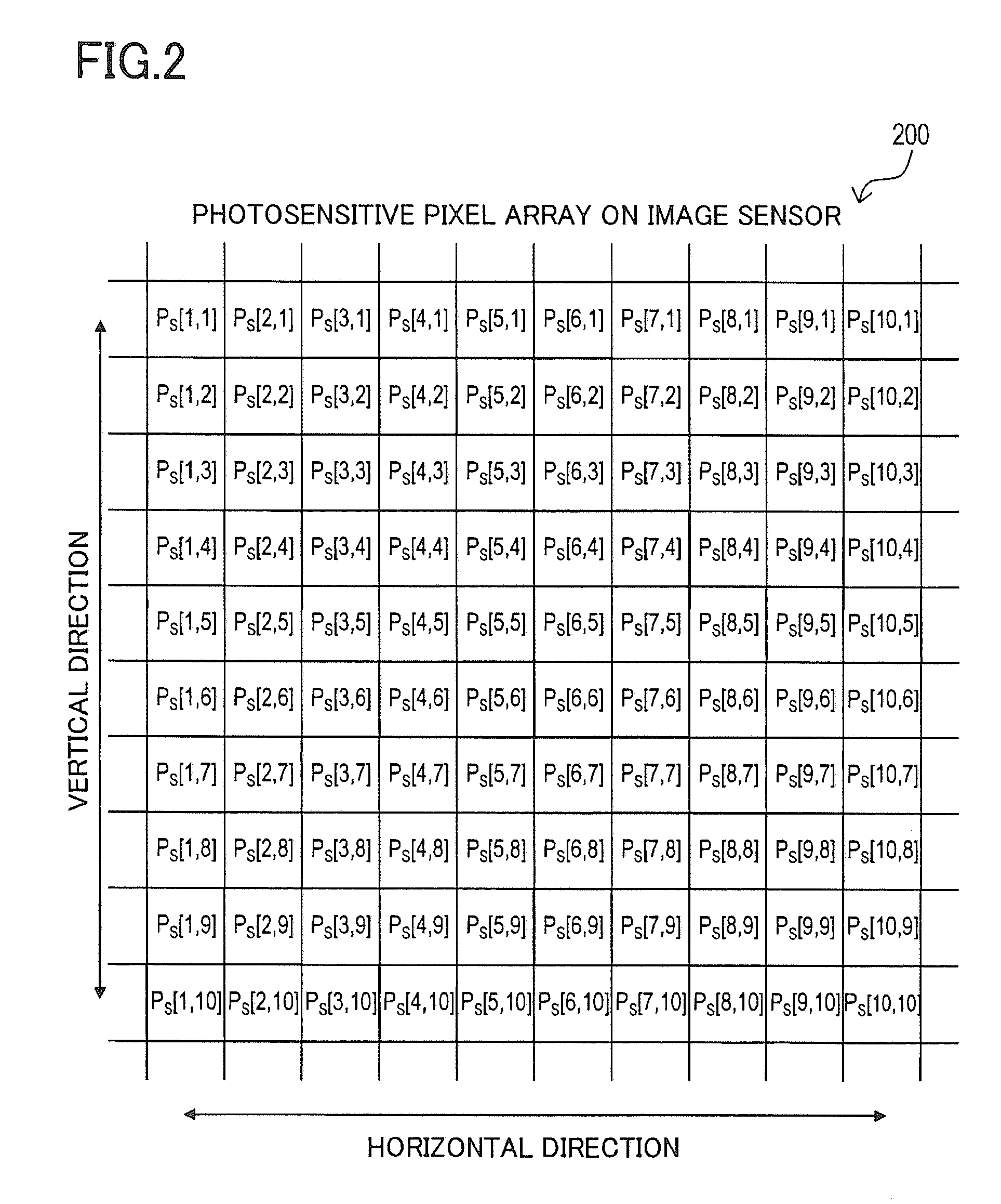
[0178]First, a first practical example (Example 1) will be described. In Example 1, adopted as the method for reading pixel signals from the image sensor 33 is a binned reading method, whereby reading proceeds concurrently with binning (adding-up) of a plurality of photosensitive pixel signals. Here, as binned reading proceeds, the binning pattern used is changed from one to the next among a plurality of binning patterns. A binning (addition) pattern denotes a specific pattern of combination of photosensitive pixels that are going to be binned together (added up). The plurality binning patterns used include two or more of a first, a second, a third, and a fourth binning pattern that are different from one another.

[0179]FIGS. 7A, 7B, 8A, and 8B...

embodiment 2

[0429]Next, a first practical example (Example 1) of a second embodiment (Embodiment 2) of the invention will be described. Unless otherwise indicated, numbered practical examples mentioned in the course of the following description of Embodiment 2 are those of Embodiment 2.

example 1

[0430]As in Example 1 of Embodiment 1, also in this practical example, a binned reading method is used to read pixel signals from the image sensor 33. The binning patterns used for that purpose are the same as those described under the heading [Binning Pattern] with respect to Example 1 of Embodiment 1, and therefore no overlapping description will be repeated. In this practical example, binned reading is performed while a plurality of binning patterns are changed from one to the next, and by blending together a plurality of color-interpolated images resulting from different binning patterns, one output blended image is generated.

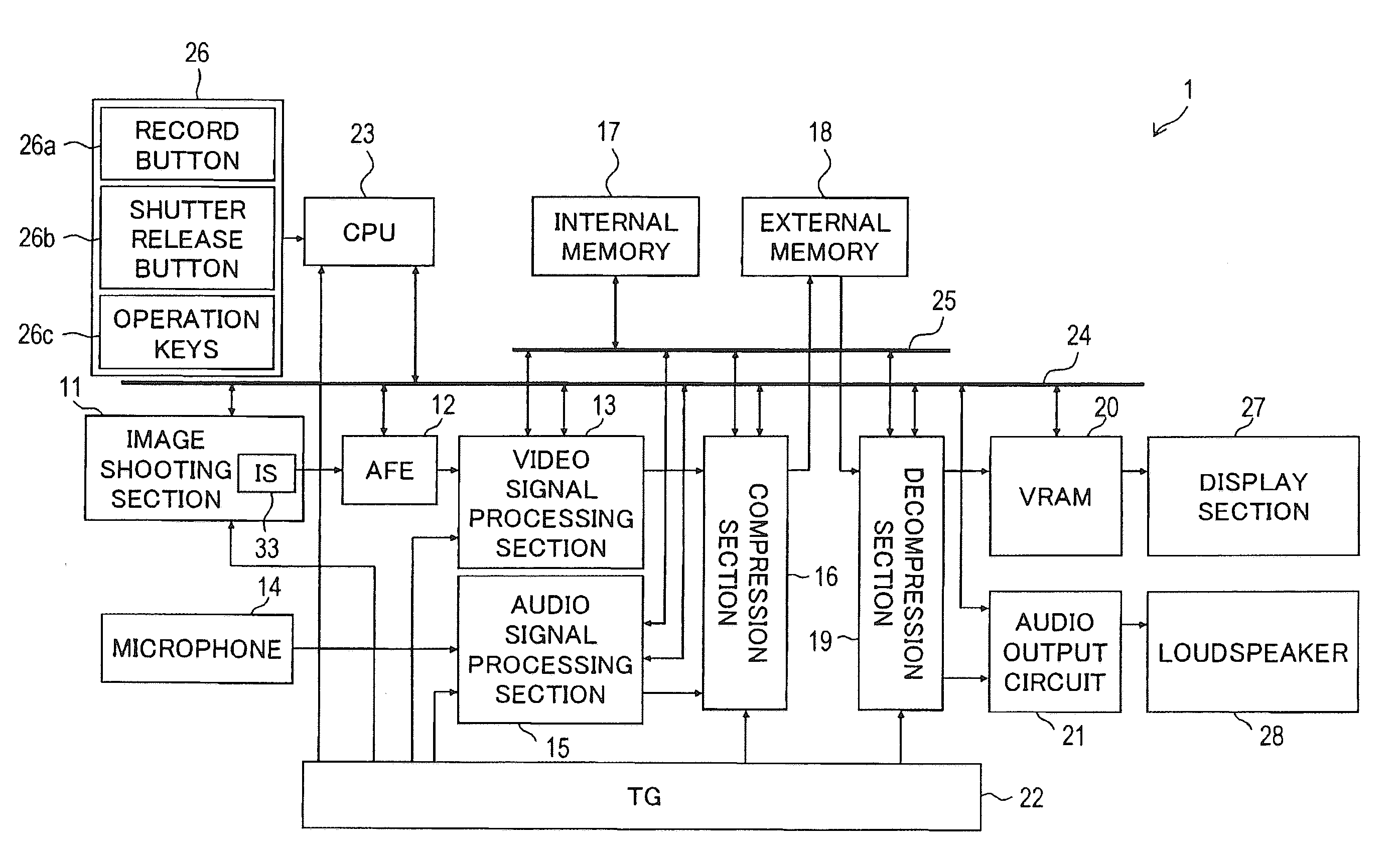
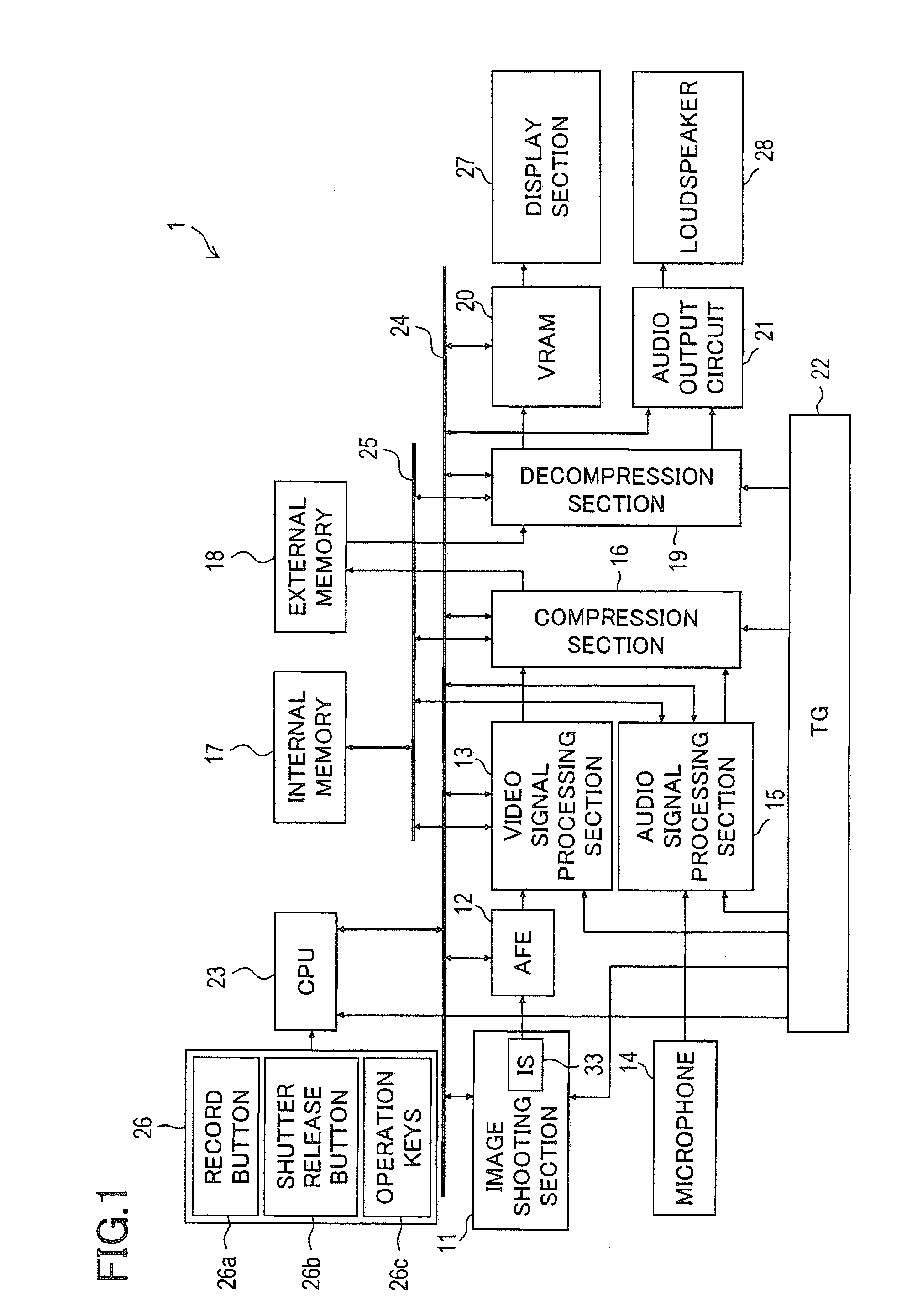
[0431]FIG. 58 is a block diagram of part of the imaging device 1 in FIG. 1, including an internal block diagram of a video signal processing section 13A, which here serves as the video signal processing section 13 in FIG. 1. The video signal processing section 13A includes blocks identified by the reference signs 151 to 154, 156, and 157.

[0432]A color inter...


PUM

PropertyMeasurementUnit
photosensitiveaaaaaaaaaa
coloraaaaaaaaaa
weight coefficient calculationaaaaaaaaaa

Abstract

A color interpolation process unit (51) successively acquires from an AFE (12), a plurality of original images in which the pixel positions having pixel signals are different and executes a color interpolation process on the original images to generate a color-interpolated image. An image synthesis unit (54) combines the color-interpolated image (current frame) to be generated and a synthesis image (previous frame) outputted previously so as to generate a synthesis image. The synthesis image is inputted to a color synchronization process unit (55) to output a video signal and stored in a frame memory (52) so as to be used for synthesis of the next frame.

Description

TECHNICAL FIELD [0001]The present invention relates to a device and a method for performing image processing on an acquired source image (original image), and also relates to an imaging device (image taking, shooting, or otherwise acquiring device) such as a digital video camera.BACKGROUND ART [0002]In a case where a moving image (motion picture, movie, video) is shot by use of an image sensor (image sensing device) that is capable of shooting a still image (still picture, photograph) with a large number of pixels, the frame rate needs to be held low in accordance with the rate at which pixel signals are read from the image sensor. To achieve a high frame rate, the amount of image data needs to be reduced by binned (additive) reading or skipped (thinned-out) reading of pixel signals.[0003]A problem here is that, while the pixel intervals on the image sensor are even in both the horizontal and vertical directions, performing binned or skipped reading causes pixel signals to be presen...

Claims


Application Information

Patent Timeline
Patent Type & Authority Applications(United States)
IPC IPC(8): H04N5/225
CPCB22D11/04B22D11/0401B22D11/07B22D11/059B22D11/049G06T3/4015H04N25/46H04N25/447H04N25/76H04N23/843H04N25/134
Inventor TSUNEKAWA, NORIKAZUOKADA, SEIJIMAENAKA, AKIHIRO
Owner SANYO ELECTRIC CO LTD
Why Eureka
Try Eureka