Pneumatic inflating device contained entirely within shoe sole

a sole and pneumatic technology, applied in the field of shoes, can solve the problems of uneven air distribution in the sole of the shoe, inability to allow differential distortion, and distortion in every direction, and achieve the effects of preventing damage, facilitating inflation, and facilitating finger operation

Active Publication Date: 2011-03-24
DOYLE HAROLD S
View PDF24 Cites 87 Cited by
  • Summary
  • Abstract
  • Description
  • Claims
  • Application Information

AI Technical Summary

Benefits of technology

[0014]Another need addressed by the invention includes providing a locking mechanism which is easily finger-operated to facilitate inflation by a shoe wearer.
[0015]Another need addressed by the invention includes providing a recess for storing the pump actuator and air release valve to prevent damage thereto.
[0016]Another need addressed by the invention includes providing a pneumatic inflation device in which the bladder and pump are complementary configured so as to minimize shoe bulk.
[0017]Still another need addressed by the invention includes providing a pneumatic inflation device entirely within a shoe sole, in which the pump is positioned to avoid excessive stress.
[0021]The inventive device can further include a locking mechanism which secures the pump actuator within the sole. It is preferred that the pump actuator can be locked only when the pump-actuator cap is flush with the outer wall of the sole. Such an arrangement facilitates use of the locking mechanism by the shoe wearer. The locking mechanism is finger-operated to further facilitate use by the shoe wearer.
[0024]The device is preferably positioned such that the pump is between the forefoot-pressure portion and the heel-pressure portion which strikes the ground first during walking or running by a typical shoe-wearer. This positioning prevents the pump from being damaged during the lifetime of the shoe.

Problems solved by technology

If the walls of the bladder are not constrained, for instance, by the structure of the sole of the shoe, the distortion occurs in every direction.
This arrangement of adhering all of the surface of the foam core limits the shape of the bladder to the shape of the foam core and does not allow for differential distortions of the bladder as the bladder is inflated.
Such prior art shoes also have not allowed for selective adjustment of the pressure in the bladder chambers and may result in uneven air distribution in the sole of the shoe.
Such prior art shoes encounter different problems in use.
Pumps positioned on the upper portion add bulk to the shoe and limit agility.
Such pumps also inhibit aesthetic choices in shoe design.
External pump actuators impose aesthetic limitations on footwear and add bulk to the “footprint” of the footwear.

Method used


Image

  • Pneumatic inflating device contained entirely within shoe sole
  • Pneumatic inflating device contained entirely within shoe sole
  • Pneumatic inflating device contained entirely within shoe sole

Examples


Embodiment Construction

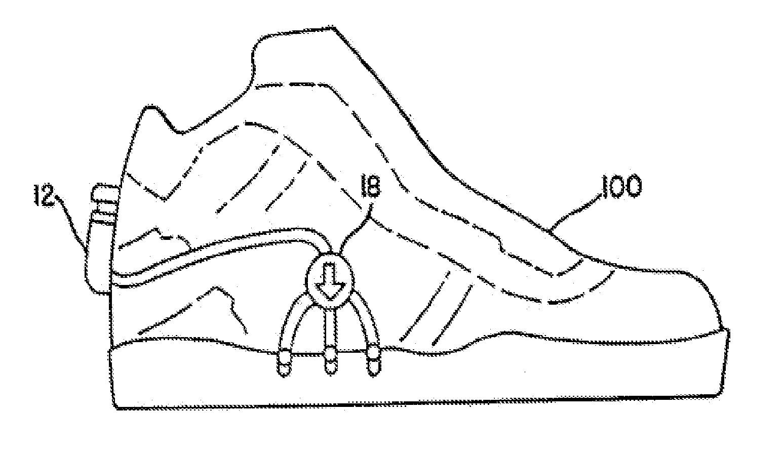
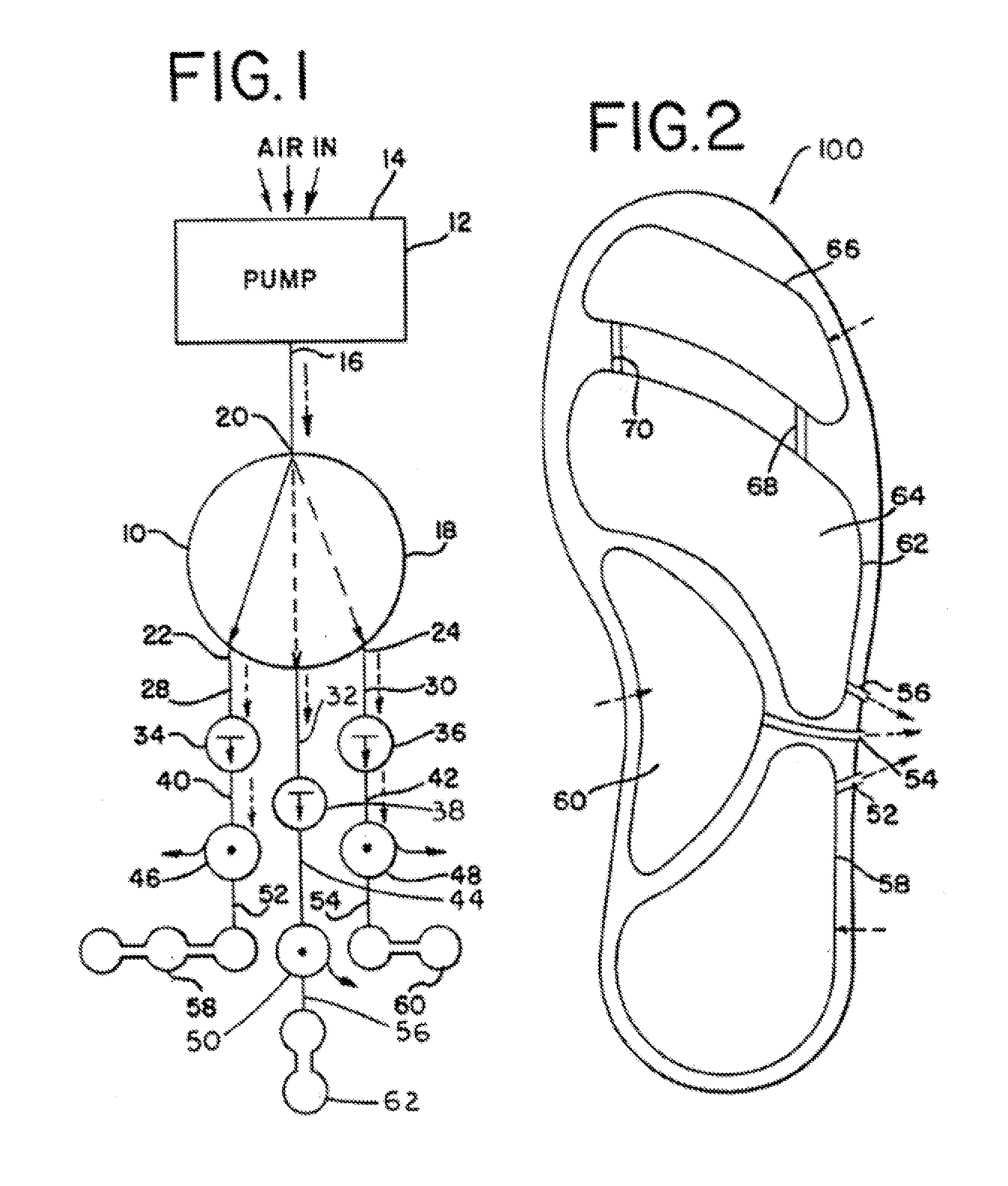
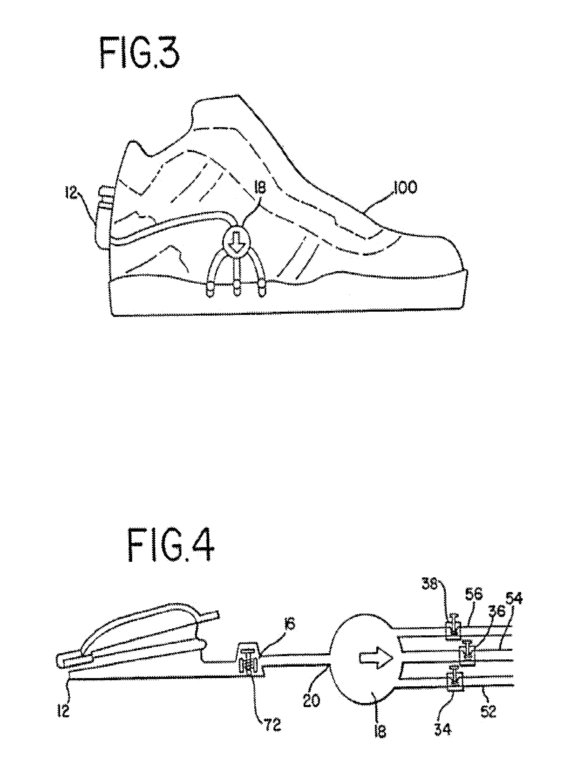
[0053]Referring now to the drawings, wherein like reference numerals designate identical or corresponding parts throughout the several views, and more particularly to FIG. 1 thereof, there is illustrated

[0054]The present invention is directed to a shoe with a pneumatic inflating device disposed therein. The general schematic of the shoe inflating arrangement is shown in FIG. 1 and includes three bladder sets. However, it will be apparent that the arrangement is adaptable to any plurality of bladder sets. The arrangement includes a pump 12 with an inlet 14 and an outlet 16. Outlet 16 is connected to a flow switching device 18 at a flow switching input 20. Flow switching device 18 operates as a selective valve which allows air flow into at least two outlets, the preferred embodiment having a first outlet 22, a second outlet 24, and a third outlet 26. Each outlet 22, 24, and 26 is connected to a corresponding conduit 28, 30, and 32. Each conduit 28, 30, and 32 is associated with corres...


PUM


Abstract

A pneumatic inflation device disposed within the sole of a shoe and comprising a pump with integral air release valve and which is entirely within the sole, a pump actuator which is entirely within the sole when not in use, and an inflatable bladder which is entirely within the sole and is operatively connected to the pump. Such a device can include a mechanism to lock the pump actuator within the sole such that the mechanism's cap is flush with the outer wall of the sole and finger-operable to allow the shoe-wearer to easily operate the inflation device and release air therefrom.

Description

CROSS REFERENCE TO RELATED DOCUMENTS[0001]The present invention claims benefit of priority to U.S. Provisional Patent Application Ser. No. 61 / 244,038 of DOYLE et al., entitled “PNEUMATIC INFLATING DEVICE CONTAINED ENTIRELY WITHIN SHOE SOLE,” filed on Sep. 19, 2009, and is related to commonly-assigned U.S. Pat. Nos. 5,222,312; 6,305,102; and 6,725,573 of Harold S. DOYLE, the entire disclosures of which are hereby incorporated by reference herein.BACKGROUND OF THE INVENTION[0002]1. Field of the Invention[0003]The present invention generally relates to shoes, and, more particularly, to pneumatic cushioning therein.[0004]2. Discussion of the Background[0005]Prior art shoes have involved a variety of inflation devices disposed at different locations. For instance, previous shoe arrangements have included soles that can be inflated at the arch to provide support. Other shoes contain soles which have sealed inflated chambers disposed within the soles in order to increase vertical bounce. T...

Claims


Application Information

Patent Timeline
Patent Type & Authority Applications(United States)
IPC IPC(8): A43B13/20
CPCA43B13/203A43B13/20A43B13/206
Inventor DOYLE, HAROLD S.
Owner DOYLE HAROLD S
Why Eureka
Try Eureka