Ventilation and air conditioning apparatus for vehicle

a technology for air conditioning apparatus and vehicle, which is applied in the direction of refrigeration components, light and heating apparatus, transportation and packaging, etc., to achieve the effect of ensuring the amount of ventilation

Active Publication Date: 2011-03-24
MITSUBISHI ELECTRIC CORP
View PDF14 Cites 15 Cited by
  • Summary
  • Abstract
  • Description
  • Claims
  • Application Information

AI Technical Summary

Benefits of technology

[0012]According to the ventilation and air conditioning apparatus for a vehicle of the present invention, even if the operation of an air conditioner is stopped, fresh outside air is supplied to inside a vehicle and thereby an amount of ventilation can be secured.

Problems solved by technology

Further, as a technique regarding a vehicle air conditioner, which aims at solving a problem that “in a vehicle air conditioner using flammable refrigerant, leaking refrigerant cannot be sometimes discharged to outside by a fan device and there is fear that the refrigerant may be leaked from an internal air introduction port into a cabin even if a door of an air delivery device is closed”, there has been proposed a vehicle air conditioner “having a configuration in which a concentration of the flammable refrigerant is prevented from arriving at a combustion range by increasing an external air introduction amount when the leakage amount of the flammable refrigerant is small and when the leakage amount of the flammable refrigerant is large, air conditioned air blowout ports 11, 12, 13 and an internal air introduction port 3 are closed to thereby completely isolate the inside of a casing 2 from the inside of the cabin and the operation of a compressor 19 is stopped” (Patent Document 2).

Method used


Image

  • Ventilation and air conditioning apparatus for vehicle
  • Ventilation and air conditioning apparatus for vehicle
  • Ventilation and air conditioning apparatus for vehicle

Examples


first embodiment

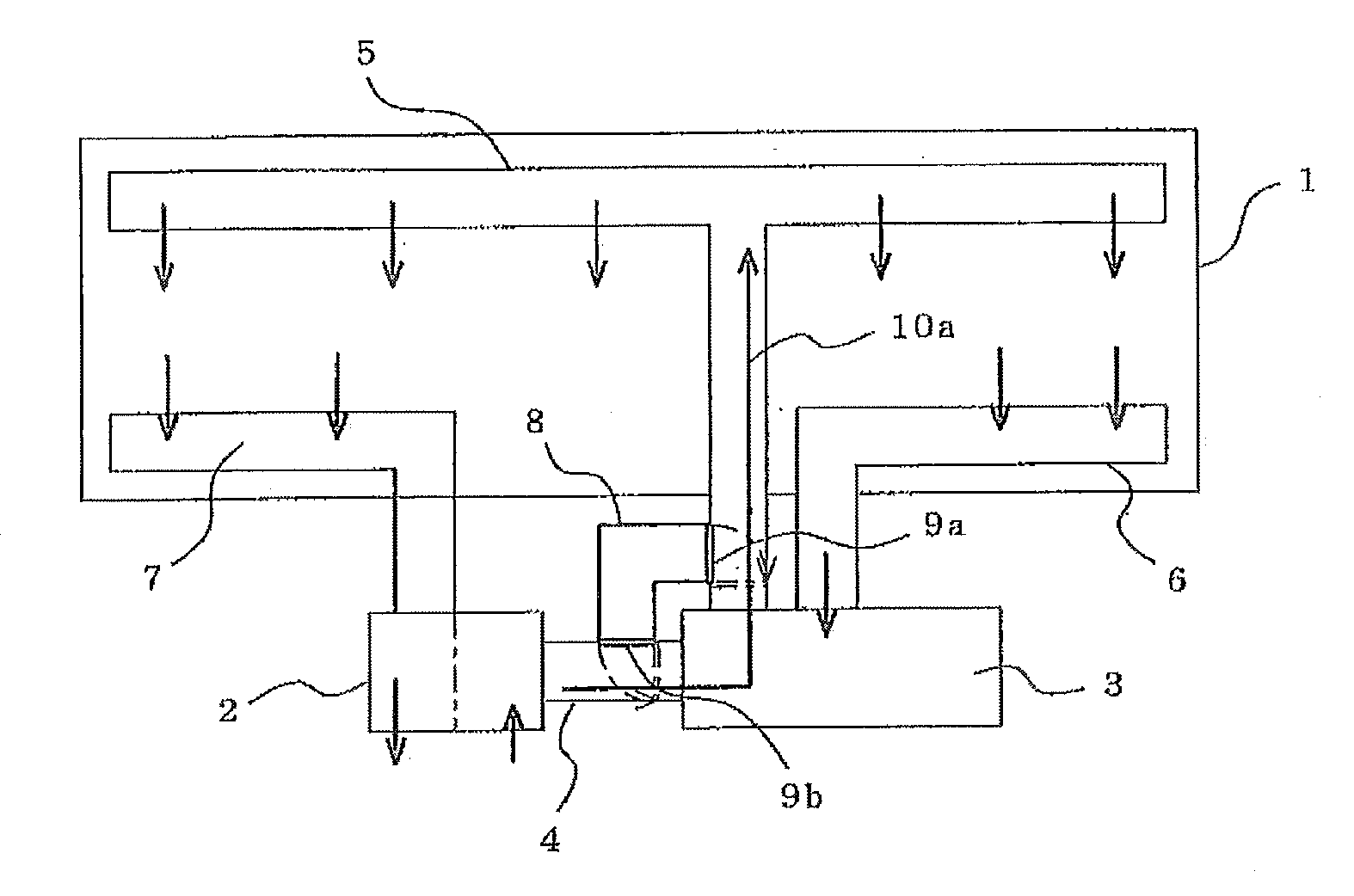
[0017]FIG. 1 is a configuration diagram of a ventilation and air conditioning apparatus for a vehicle according to a first embodiment 1 of the present invention.

[0018]In FIG. 1, reference numeral 1 denotes a vehicle, 2 denotes a ventilator, 3 denotes an air conditioner, 4 denotes a duct for fresh outside air, 5 denotes a duct for conditioned air, 6 denotes a return flow duct, 7 denotes an exhaust duct, 8 denotes a bypass duct, 9a denotes a first damper, 9b denotes a second damper, and 10a denotes an air flow direction at the normal time.

[0019]The ventilator 2 sucks air inside the vehicle through the exhaust duct 7 and discharges the air outside the vehicle.

[0020]Further, the ventilator 2 sucks fresh air outside the vehicle and supplies the fresh air to the air conditioner 3 through the duct 4 for fresh outside air or supplies the fresh air inside the vehicle through the bypass duct 8 and duct 5 for conditioned air. This air flow will be described later again.

[0021]The air conditione...

second embodiment

[0062]As a second embodiment of the present invention, a configuration example of the air conditioner 3 will be described. The configurations of other components are the same as those in the first embodiment.

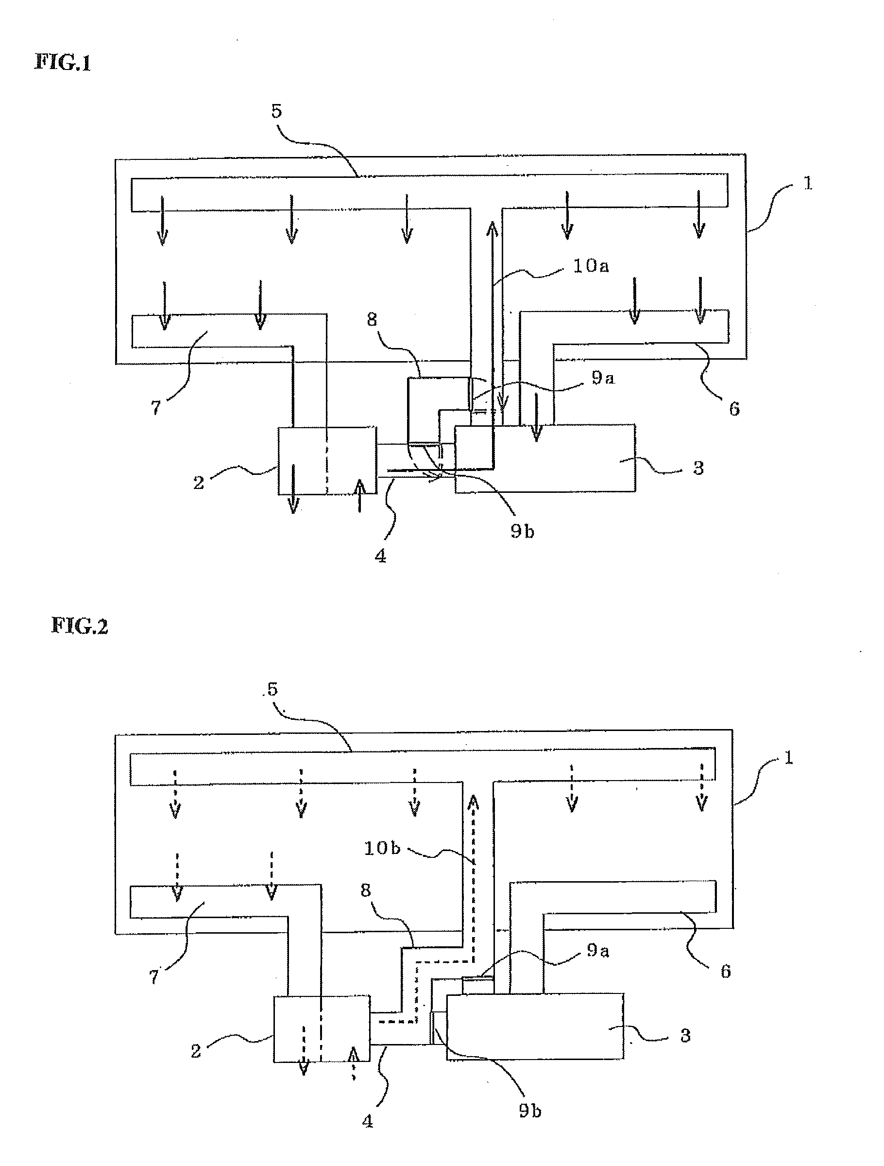
[0063]FIG. 3 is an internal configuration diagram of the air conditioner 3.

[0064]In FIG. 3, reference numeral 11 denotes a compressor, 12 denotes an outdoor heat exchanger, 13 denotes a capillary tube, 14 denotes an indoor heat exchanger, 15 denotes a refrigerant pipe, 16 denotes an outdoor blower, 17 denotes an indoor blower, 18 denotes an air conditioning controller, 19 denotes a refrigerant pressure sensor, 20a denotes an air temperature sensor provided on the upstream side of the outdoor heat exchanger, 20b denotes an air temperature sensor provided on the upstream side of the indoor heat exchanger, and 21 denotes a compressor current sensor.

[0065]The air conditioner 3 has a vapor compression refrigeration cycle constituted by the compressor 11, outdoor heat exchanger 12, ca...

third embodiment

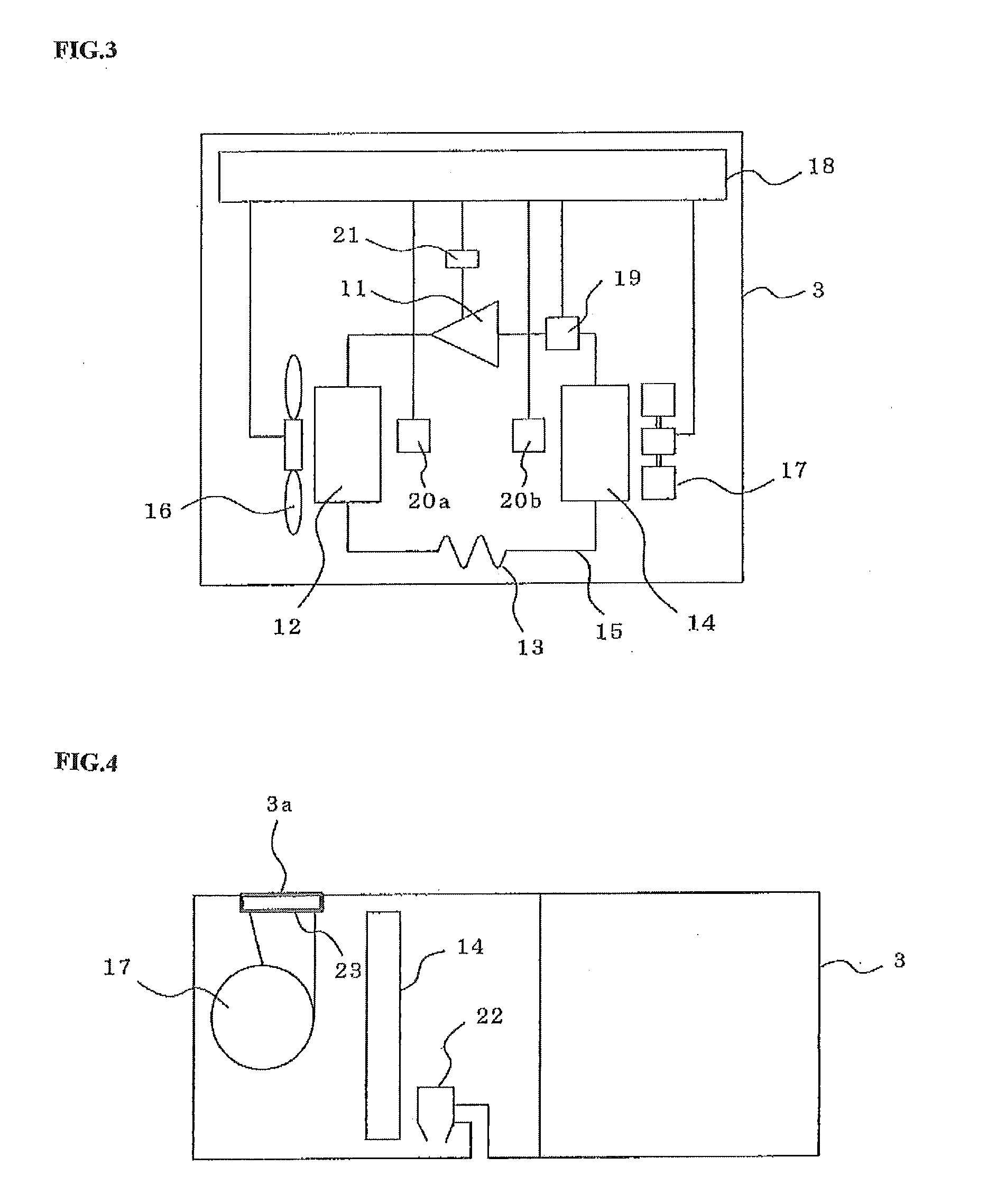
[0078]FIG. 4 is a traverse cross-sectional view of the air conditioner 3 according to a third embodiment of the present invention.

[0079]In FIG. 4, reference numeral 22 denotes a drain pump for discharging condensed water accumulated in the lower portion of the indoor heat exchanger 14 from the bottom surface of the air conditioner to the outside of the vehicle. The drain pump 22 operates according to an instruction from the air conditioning controller 18. Reference numeral 23 denotes an ultraviolet lamp provided in the vicinity (e.g., blowout port of the indoor blower 17) of a blowout port 3a of the air conditioner 3. The ultraviolet lamp is always turned ON during operation of the air conditioner 3 and, when a refrigerant leakage has occurred in the air conditioner 3, the refrigerant flowing from the air conditioner 3 into the duct 5 for conditioned air is decomposed by ultraviolet ray emitted from the ultraviolet lamp.

[0080]Other components not shown in FIG. 4 have the same config...


PUM


Abstract

A ventilation and air conditioning apparatus for a vehicle includes: a ventilator that sucks air from outside the vehicle; an air conditioner that conditions air inside the vehicle; a duct for fresh outside air that connects the ventilator with the air conditioner so as to supply the air that the ventilator has sucked from outside the vehicle to the air conditioner; and a duct for conditioned air that supplies the conditioned air blown out from the air conditioner to inside the vehicle. The duct for fresh outside air is branched so as to be connected to the duct for conditioned air. With this configuration, even if the operation of the air conditioner is stopped due to, e.g., a leakage of a flammable refrigerant, an amount of ventilation can be secured in the vehicle.

Description

TECHNICAL FIELD[0001]The present invention relates to a ventilation and air conditioning apparatus for a vehicle installed in a vehicle such as a railway.BACKGROUND ART[0002]As a technique regarding a vehicle ventilator, which aims at “simplifying structure to reduce labor in manufacturing, securing appropriate air quantity and air speed while maintaining predetermined air conditioning performance, and reducing noise”, there has been proposed a vehicle ventilator provided with: a first duct arranged in the upper part of a vehicle so as to supply conditioned air from an air conditioning means into a cabin; a second duct arranged in the lower part of the vehicle so as to suck air inside the cabin for returning; a third duct arranged in the lower part of the vehicle so as to suck air inside the cabin for leading it to an exhaust means; an air conditioning means arranged under the floor so as to mix return air from the second duct with air from outside the cabin sucked in by suction mea...

Claims


Application Information

Patent Timeline
Patent Type & Authority Applications(United States)
IPC IPC(8): F25B49/00B60H1/26
CPCB61D27/0018B60H1/00978
Inventor SHIRAISHI, KAZUHIKOTANIGUCHI, HIROKAZUSUMIDA, YOSHIHIRONISHIDA, AKIHIROYOSOMIYA, MASATOYAMASHITA, TETSUYAOKAZAKI, TAKASHI
Owner MITSUBISHI ELECTRIC CORP
Why Eureka
Try Eureka