Image processing apparatus and image processing method

Active Publication Date: 2011-03-24
OLYMPUS CORP
View PDF5 Cites 24 Cited by
  • Summary
  • Abstract
  • Description
  • Claims
  • Application Information

AI Technical Summary

Problems solved by technology

A three-plate imaging device is expensive because its conf

Method used


Image

  • Image processing apparatus and image processing method
  • Image processing apparatus and image processing method
  • Image processing apparatus and image processing method

Examples


first embodiment

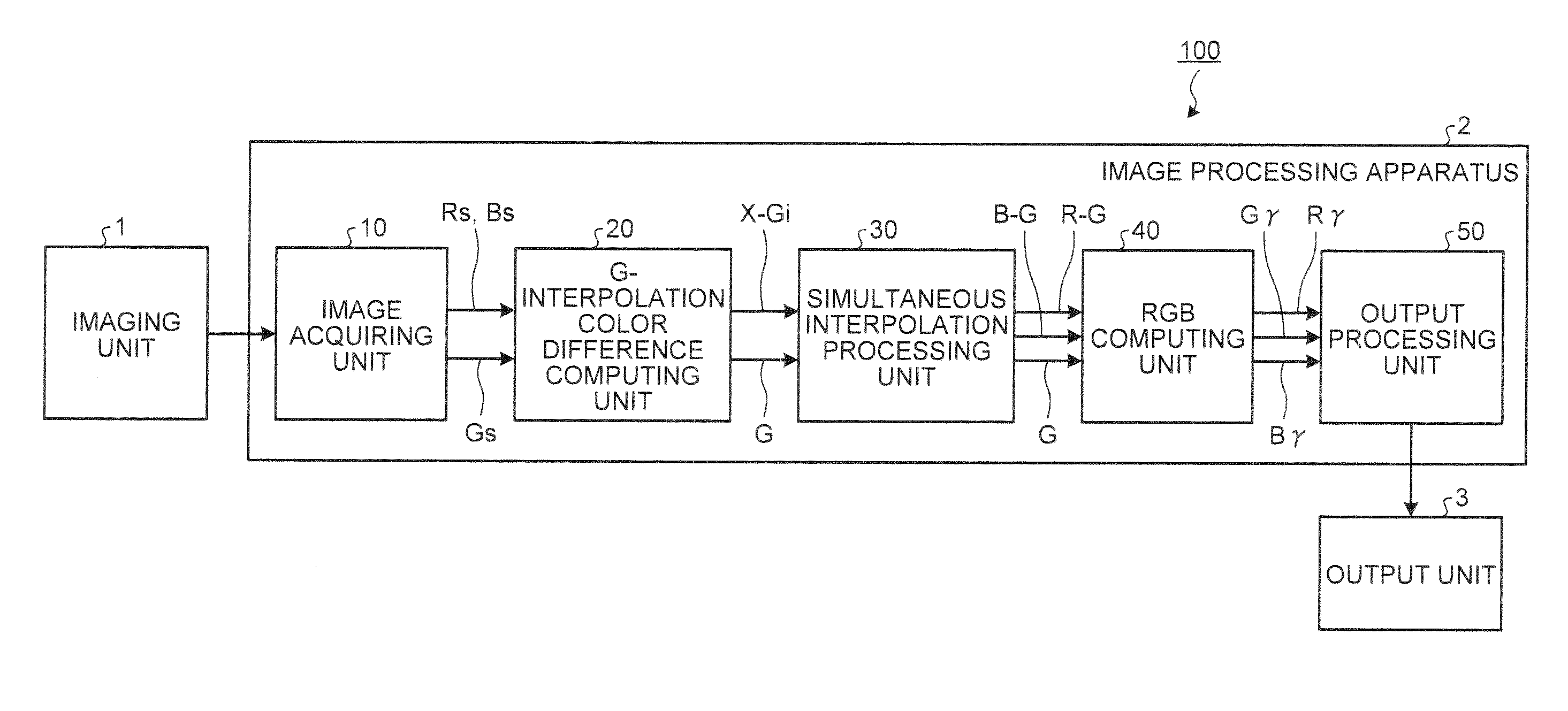
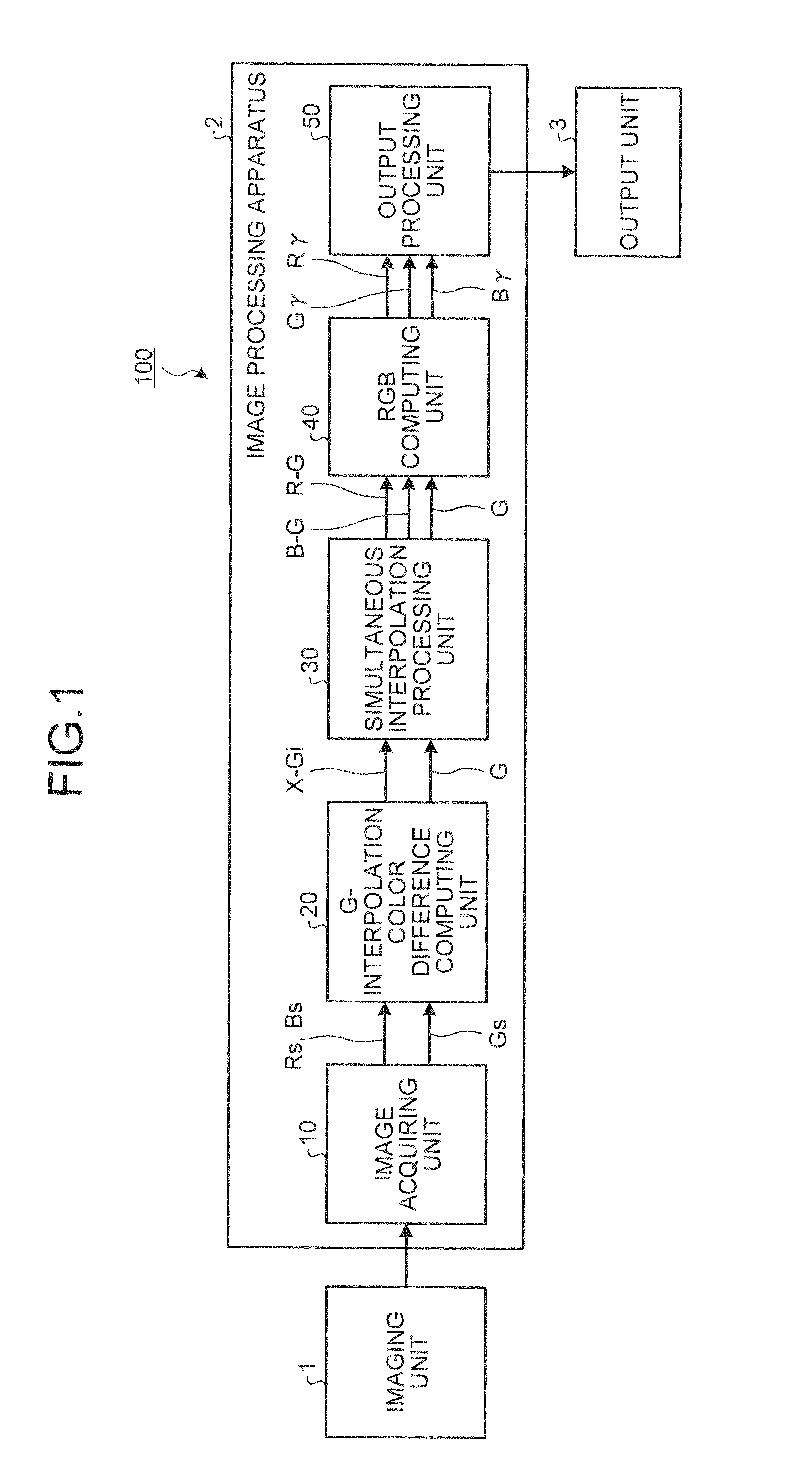
[0052]FIG. 1 is a block diagram typically illustrating an example configuration of an image output apparatus 100 that includes an image processing apparatus according to the first embodiment of the present invention. As illustrated in FIG. 1, the image output apparatus 100 according to the first embodiment includes an imaging unit 1 that captures an image of a subject, an image processing apparatus 2 that performs various types of image processing on the image captured by the imaging unit 1, and an output unit 3 that outputs the image processed by the image processing apparatus 2.

[0053]The imaging unit 1 is realized by using an optical system such as a lens, an IR cut filter, and an optical low pass filter, an imaging device such as a CCD image sensor and a CMOS image sensor, a drive control unit of the imaging device, and the like. In the imaging unit 1, the lens concentrates light of a subject on a light receiving unit of the imaging device to form an optical image of the subject ...

first alternative example of first embodiment

[0221]Next, it will be explained about the first alternative example of the first embodiment of the present invention. In the first embodiment described above, it has been explained about the case where the image processing apparatus modifies an interpolation process type of a processing-target G-missing pixel position on the basis of a counting process result of interpolation process types of a plurality of peripheral G-missing pixel positions located at the vicinity of the processing-target G-missing pixel position. In the first alternative example, the image processing apparatus modifies an interpolation process type of the processing-target G-missing pixel position on the basis of array patterns of interpolation process types of the plurality of peripheral G-missing pixel positions.

[0222]FIG. 23 is a block diagram typically illustrating an example configuration of a type information modifying unit 128 of an image processing apparatus according to the first alternative example of...

second alternative example of first embodiment

[0248]Next, it will be explained about the second alternative example of the first embodiment of the present invention. According to the first embodiment described above, it has been explained about the case where the interpolation process types of the G-missing pixel position are three kinds of the vertical interpolation process, the horizontal interpolation process, and the four-pixel average interpolation process. According to the second alternative example, the interpolation process types are five kinds of interpolation processes by further adding a diagonal interpolation process that is an interpolation process in an upward-sloping (slash) direction and an inverted diagonal interpolation process that is an interpolation process in a downward-sloping (backslash) direction.

[0249]FIG. 27 is a block diagram typically illustrating an example configuration of a G-interpolation color difference computing unit 120 of an image processing apparatus according to the second alternative exa...


PUM


Abstract

An image processing apparatus includes a determining unit, a modifying unit, a selecting unit, and a generating unit. The determining unit determines, with respect to a missing pixel position that does not have a signal of a specified color among colors forming an image, an interpolation process type indicating the type of an interpolation process of the signal of the specified color. The modifying unit modifies the determined interpolation process type based on interpolation process types of peripheral missing pixel positions located at the vicinity of the missing pixel position. The selecting unit selects a color-difference signal that is a difference between signal of a color except the specified color and the signal of the specified color in correspondence with the modified interpolation process type. The generating unit generates an interpolation signal of the signal of the specified color at the missing pixel position based on the color-difference signal.

Description

CROSS-REFERENCE TO RELATED APPLICATIONS[0001]This application is based upon and claims the benefit priority from Japanese Patent Application No. 2009-189387, filed on Aug. 18, 2009, the entire contents of which are incorporated herein by reference.BACKGROUND OF THE INVENTION[0002]1. Field of the Invention[0003]The present invention relates to an image processing apparatus and an image processing method. More particularly, the present invention relates to an image processing apparatus and an image processing method that are used for processing an image of which each pixel consists of one color signal and generating an image of which each pixel at the same position consists of plurality of color signals.[0004]2. Description of the Related Art[0005]Various types of electronic image capturing apparatuses such as a digital camera or a digital video camera that captures an image of a subject have conventionally appeared. The configuration of an imaging device that is built in an electroni...

Claims


Application Information

Patent Timeline
IPC IPC(8): H04N5/228G06K9/00
CPCH04N9/045H04N2209/046H04N9/07H04N23/843H04N25/134H04N23/12
Inventor SASAKI, HIROSHI
Owner OLYMPUS CORP
Why Eureka
Try Eureka