
Cylindrical heating element and fixing device

Active Publication Date: 2011-03-24
KONICA MINOLTA BUSINESS TECH INC
View PDF26 Cites 9 Cited by
  • Summary
  • Abstract
  • Description
  • Claims
  • Application Information

AI Technical Summary

Benefits of technology

[0010]A first object of the present invention is to provide a heating element which can be utilized as a heat source for a rotating member for heating in a fixing device which is employed in an image forming device operated by an electrophotographic system, electrostatic recording system or like system, and passes a recording medium on which an unfixed toner image is held through a nip formed by the

Problems solved by technology

Therefore, according to the heat-source portion comprising the hollow metal shaft 911 having the heater H incorporated therein, it takes much time to heat the surface of the rotating member for heating 91 to a temperature at which the toner image is fused with heating and is fix

Method used


Image

  • Cylindrical heating element and fixing device
  • Cylindrical heating element and fixing device
  • Cylindrical heating element and fixing device

Examples


Embodiment Construction

[0042]Embodiments of the present invention will be described below.

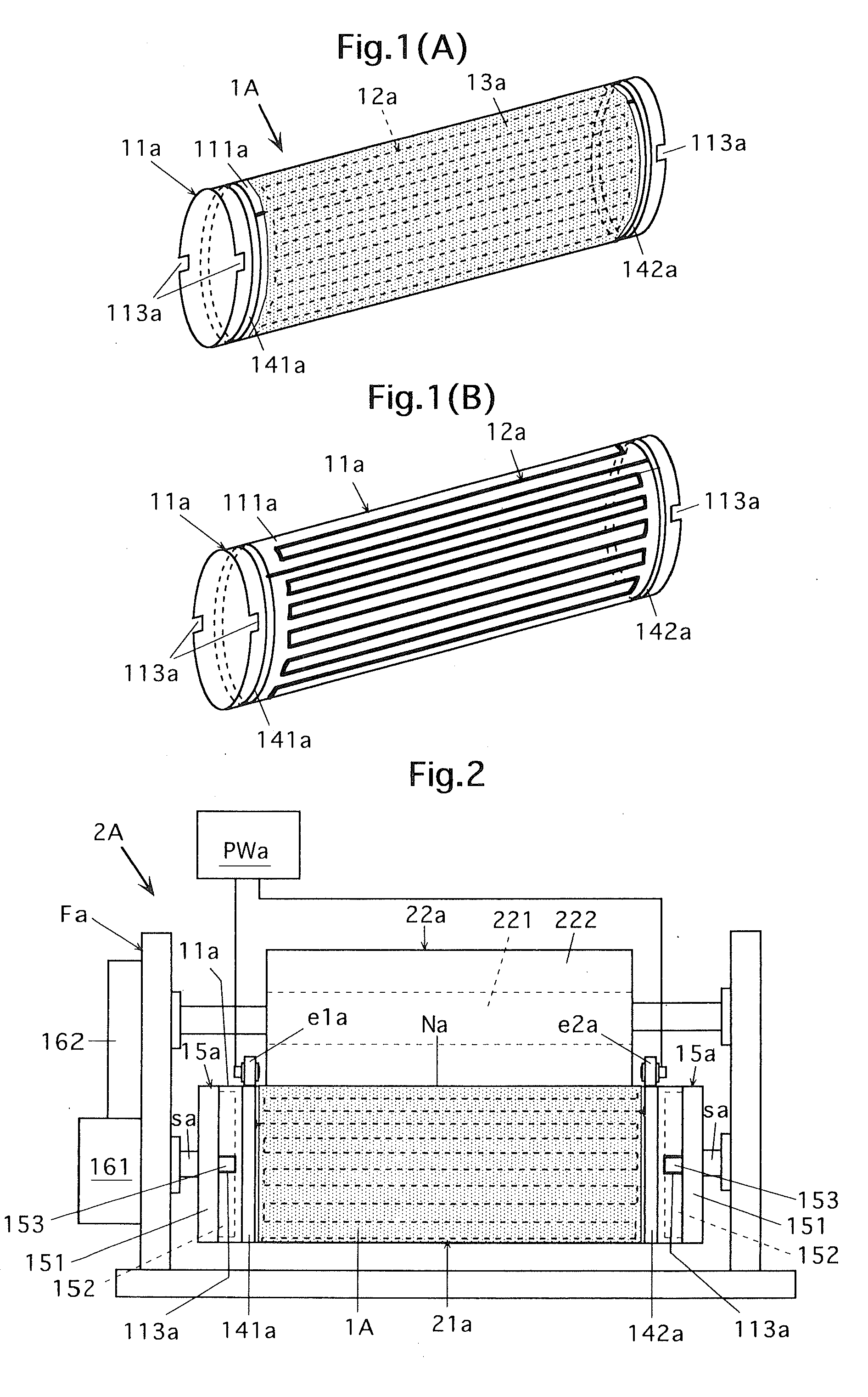
[0043]Cylindrical heating elements of the embodiments of the present invention include the following cylindrical heating element.

[0044]A cylindrical heating element comprising:

[0045]a cylindrical member;

[0046]a metallic pattern provided on at least one of outer and inner circumferential surfaces of the cylindrical member, which is capable of generating heat by being electrified; and

[0047]a resistive pattern or detecting temperature provided on at least one of the outer and inner circumferential surfaces of the cylindrical member.

[0048]Herein, the “metallic pattern which is capable of generating heat by being electrified” means a pattern comprising a metal line which can generate heat by supplying it with an electric current (in other words, an electric power).

[0049]The “resistive pattern for detecting temperature” means a pattern which is made of a conductive line or the like whose electric resistance varies dependin...


PUM


Abstract

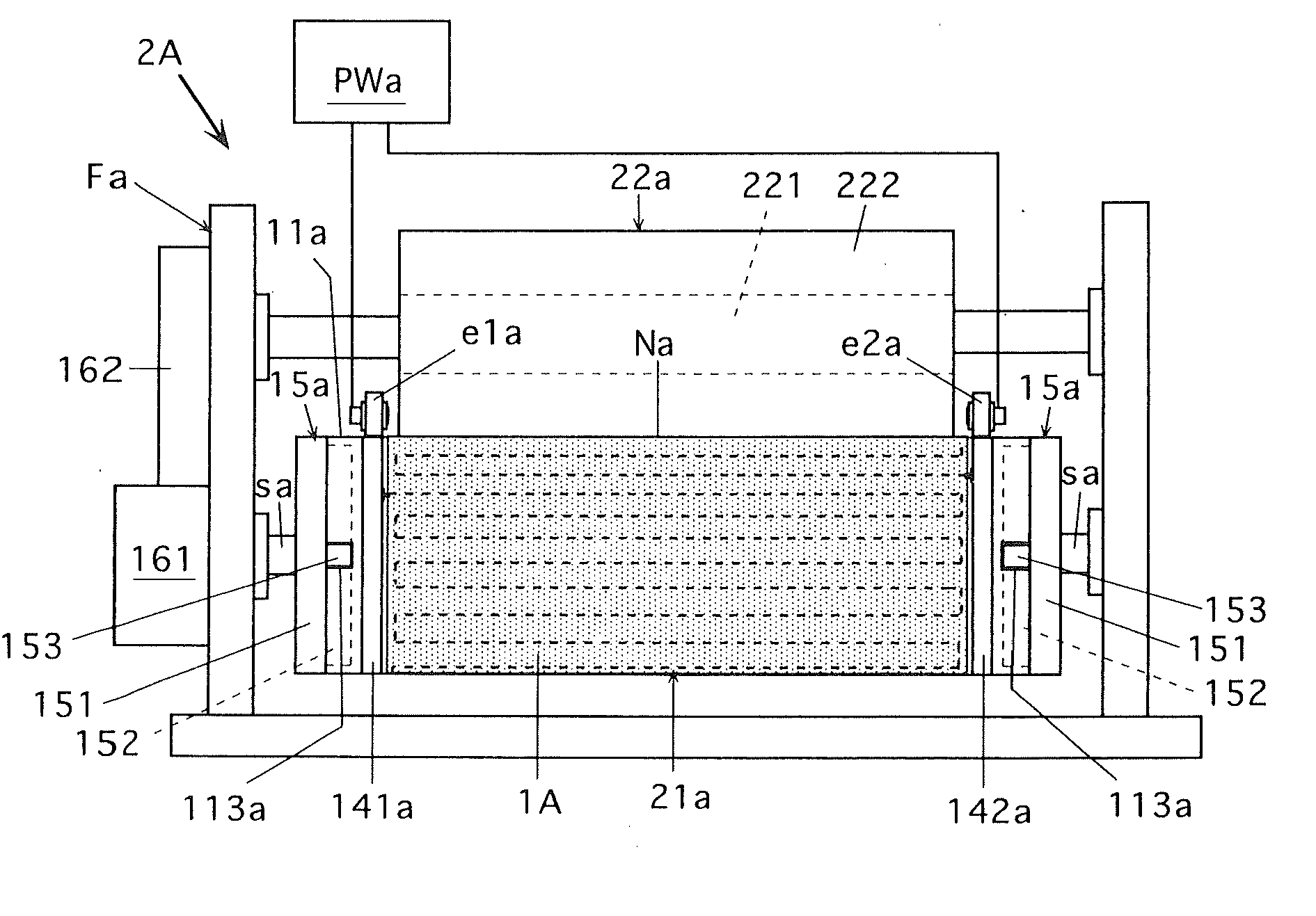
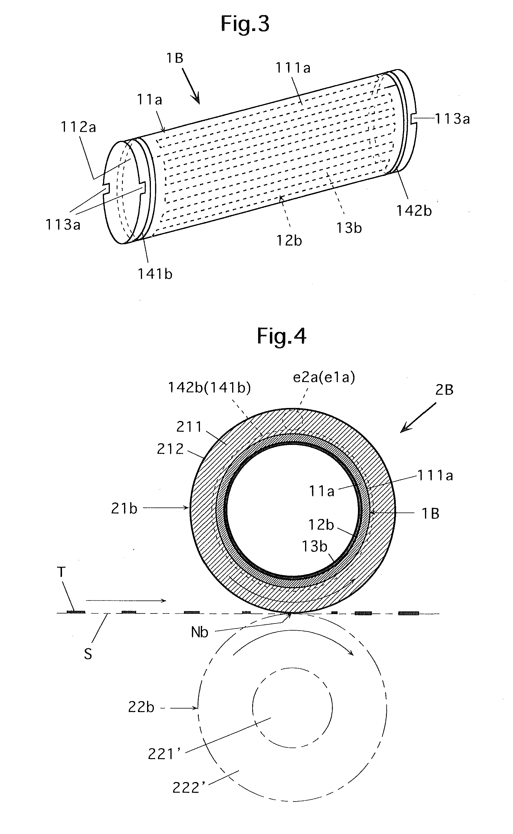
A cylindrical heating element comprising a cylindrical member, a metallic pattern provided on at least one of outer and inner circumferential surfaces of the cylindrical member, which is capable of generating heat by being electrified, and a resistive pattern for detecting temperature provided on at least one of the outer and inner circumferential surfaces of the cylindrical member. A fixing device which passes a recording medium on which an unfixed toner image is held through a nip formed by a rotating member for heating and a rotating member for pressurizing which is pressed against the rotating member for heating to fix the toner image on the recording medium with heating under pressure, the rotating member for heating comprising the cylindrical heating element.

Description

CROSS-REFERENCE TO RELATED APPLICATION[0001]This invention is based on Japanese patent application No. 2009-216713 filed in Japan on Sep. 18, 2009, the entire content of which is hereby incorporated by reference.BACKGROUND OF THE INVENTION[0002]1. Field of the Invention[0003]The present invention relates to a heating element which can be used as a rotating member for heating or a part thereof in a fixing device employed in an image forming device operated by an electrophotographic system, electrostatic recording system and other systems, that is, a fixing device which fixes, on a recording medium such as a recording paper sheet, a toner image formed in an image forming portion of the image forming device and transferred onto the recording medium by passing the recording medium (on which an unfixed toner image is held) through a nip formed by the rotating member for heating and a rotating member for pressurizing which is pressed against the rotating member for heating with heating un...

Claims


Application Information

Patent Timeline
IPC IPC(8): G03G15/20H05B1/00H05B3/10
CPCG03G15/2053G03G2215/2048H05B3/0095H05B3/34G03G15/2039H05B2203/005H05B2203/011H05B2203/013H05B2203/004
Inventor MIZUMO, YOSHIYUKI
Owner KONICA MINOLTA BUSINESS TECH INC
Learn More