Semiconductor Device and Method of Dissipating Heat From Thin Package-on-Package Mounted to Substrate

Active Publication Date: 2011-03-31
STATS CHIPPAC LTD
View PDF74 Cites 28 Cited by
  • Summary
  • Abstract
  • Description
  • Claims
  • Application Information

AI Technical Summary

Benefits of technology

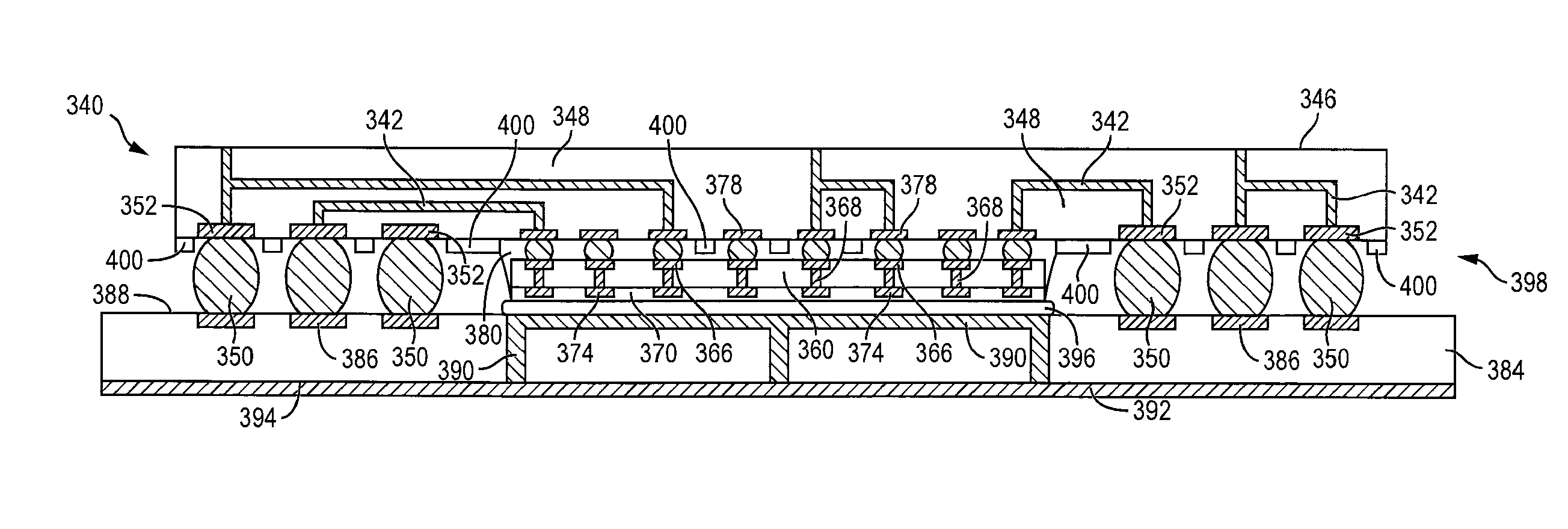
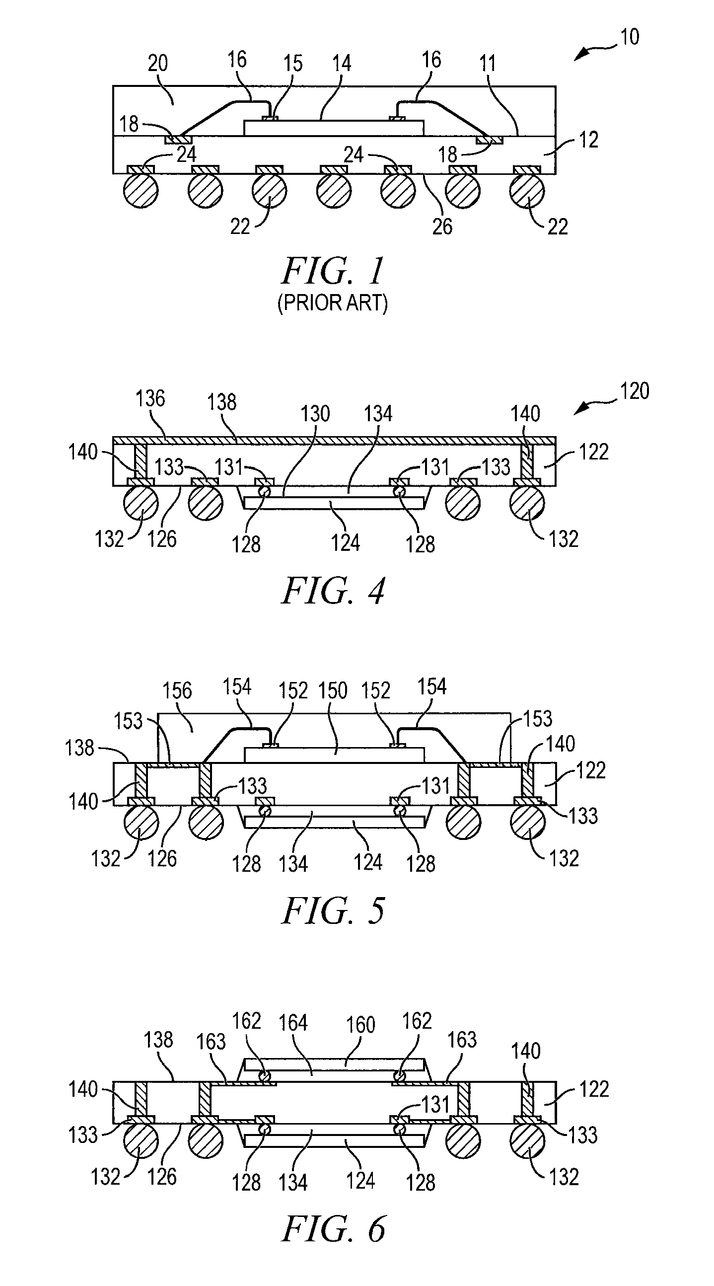
[0013]A need exists for a package structure that circumvents the above obstacles and provides for further package miniaturization, improved high-speed operation, and effective power dissipation. Accordingly, in one embodiment, the present invention is a method of making a semiconductor device comprising the steps of providing a first substrate having a central region, forming a plurality of bumps around a periphery of the central region of the first substrate, mounting a first semiconductor die to the central region of the first substrate, and mounting a seco

Problems solved by technology

High frequency and high power consumption semiconductor devices generally generate more heat.
Without effective heat dissipation, the generated heat can reduce performance, decrease reliability, and reduce the useful lifetime of the semiconductor device.
Further reduction of package thickness is increasingly difficult in part due to the fact that wire bonding interconnection employs wire loops of finite height imposing lower limits on size in the “Z” direction) and finite span imposing lower limits on size

Method used


Image

  • Semiconductor Device and Method of Dissipating Heat From Thin Package-on-Package Mounted to Substrate
  • Semiconductor Device and Method of Dissipating Heat From Thin Package-on-Package Mounted to Substrate
  • Semiconductor Device and Method of Dissipating Heat From Thin Package-on-Package Mounted to Substrate

Examples


Example

DETAILED DESCRIPTION OF THE DRAWINGS

[0028]The present invention is described in one or more embodiments in the following description with reference to the figures, in which like numerals represent the same or similar elements. While the invention is described in terms of the best mode for achieving the invention's objectives, it will be appreciated by those skilled in the art that it is intended to cover alternatives, modifications, and equivalents as may be included within the spirit and scope of the invention as defined by the appended claims and their equivalents as supported by the following disclosure and drawings.

[0029]Semiconductor devices are generally manufactured using two complex manufacturing processes: front-end manufacturing and back-end manufacturing. Front-end manufacturing involves the formation of a plurality of die on the surface of a semiconductor wafer. Each die on the wafer contains active and passive electrical components, which are electrically connected to f...


PUM


Abstract

A semiconductor device has a first substrate with a central region. A plurality of bumps is formed around a periphery of the central region of the first substrate. A first semiconductor die is mounted to the central region of the first substrate. A second semiconductor die is mounted to the first semiconductor die over the central region of the first substrate. A height of the first and second die is less than or equal to a height of the bumps. A second substrate has a thermal conduction channel. A surface of the second semiconductor die opposite the first die is mounted to the thermal conductive channel of the second substrate. A thermal interface layer is formed over the surface of the second die. The bumps are electrically connected to contact pads on the second substrate. A conductive plane is formed over a surface of the second substrate.

Description

CLAIM TO DOMESTIC PRIORITY[0001]The present application is a continuation-in-part of U.S. application Ser. No. 10 / 960,893, filed Oct. 7, 2004, and claims priority to the foregoing application pursuant to 35 U.S.C. §120.FIELD OF THE INVENTION[0002]Semiconductor devices are commonly found in modern electronic products. Semiconductor devices vary in the number and density of electrical components. Discrete semiconductor devices generally contain one type of electrical component, e.g., light emitting diode (LED), small signal transistor, resistor, capacitor, inductor, and power metal oxide semiconductor field effect transistor (MOSFET). Integrated semiconductor devices typically contain hundreds to millions of electrical components. Examples of integrated semiconductor devices include microcontrollers, microprocessors, charged-coupled devices (CCDs), solar cells, and digital micro-mirror devices (DMDs).[0003]Semiconductor devices perform a wide range of functions such as signal processi...

Claims


Application Information

Patent Timeline
IPC IPC(8): H01L23/00H01L21/98
CPCH01L21/563H01L23/3128H01L23/49816H01L23/49827H01L23/5389H01L23/66H01L24/16H01L24/29H01L24/32H01L24/48H01L24/81H01L24/83H01L24/95H01L25/0657H01L25/18H01L2224/16225H01L2224/32145H01L2224/48091H01L2224/48095H01L2224/48105H01L2224/48227H01L2224/48228H01L2224/4823H01L2224/48247H01L2224/73203H01L2224/73204H01L2224/73253H01L2224/73265H01L2224/81194H01L2224/812H01L2224/81801H01L2224/8383H01L2225/0651H01L2225/06513H01L2225/06517H01L2225/06541H01L2924/01013H01L2924/01029H01L2924/0103H01L2924/01047H01L2924/0105H01L2924/01078H01L2924/01079H01L2924/01082H01L2924/13091H01L2924/14H01L2924/1433H01L2924/15174H01L2924/15192H01L2924/15311H01L2924/1532H01L2924/19041H01L2924/19042H01L2924/19043H01L2924/3011H05K1/141H05K1/181H05K1/185H05K2201/10515H05K2201/1053H01L2924/01005H01L2924/01006H01L2924/01074H01L2924/01322H01L2924/014H01L2224/16145H01L2224/32225H01L2225/06589H01L2924/15321H01L2224/26175H01L2924/12041H01L2924/1306H01L2224/16235H01L2924/00014H01L2924/00H01L2924/00012H01L2924/181H01L24/73H01L2224/16146Y02P70/50H01L2224/45099H01L2224/45015H01L2924/207
Inventor PENDSE, RAJENDRA D.
Owner STATS CHIPPAC LTD
Why Eureka
Try Eureka