

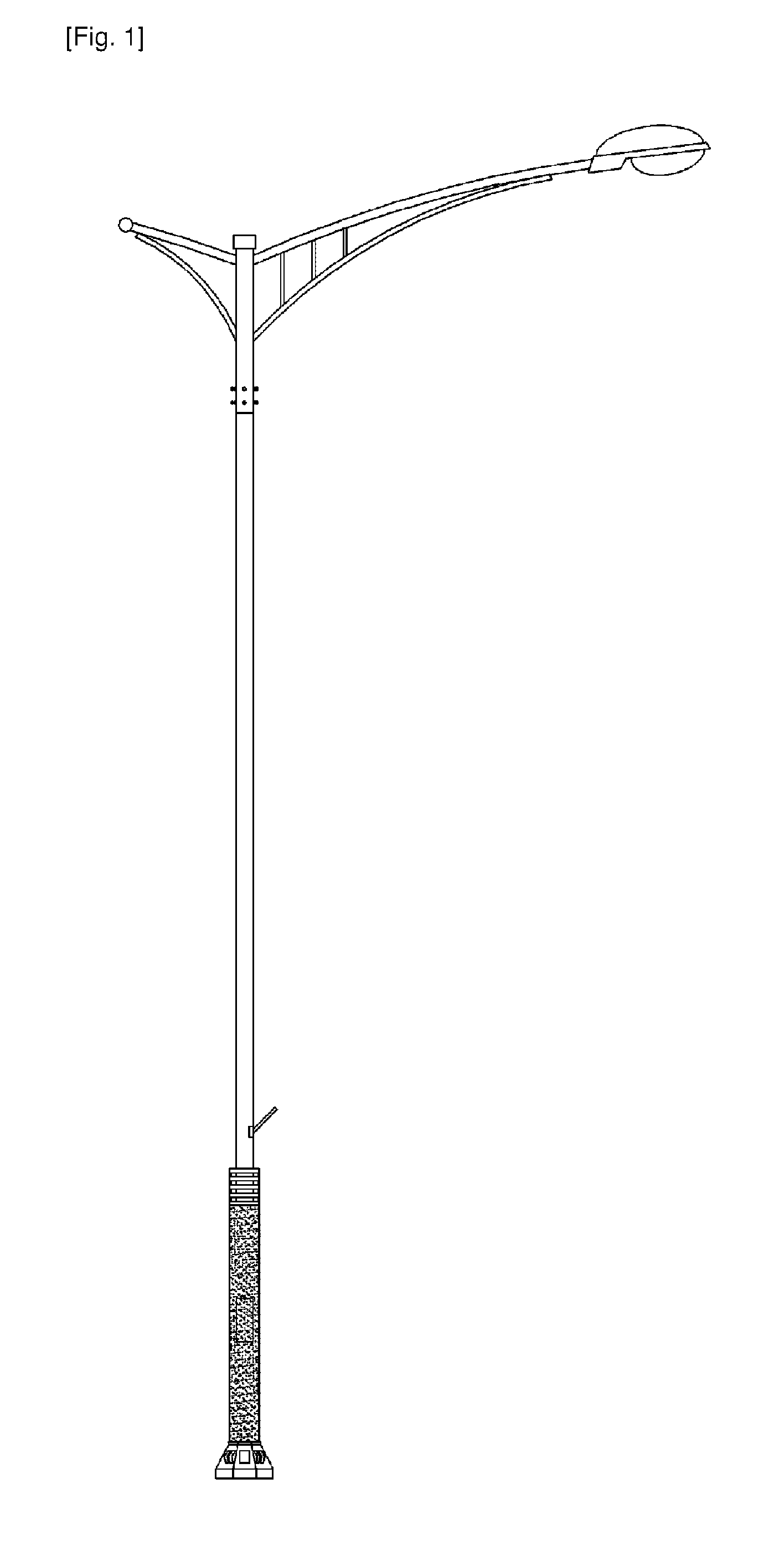
Street lamp using leds
a technology of led lights and street lamps, applied in the direction of semiconductor devices for light sources, fixed installations, lighting and heating apparatus, etc., to achieve the effect of minimizing the influence of plants and easy and efficient adjustment of lighting directions
- Summary
- Abstract
- Description
- Claims
- Application Information
AI Technical Summary
Benefits of technology
Problems solved by technology
Method used
Image

Examples
first embodiment
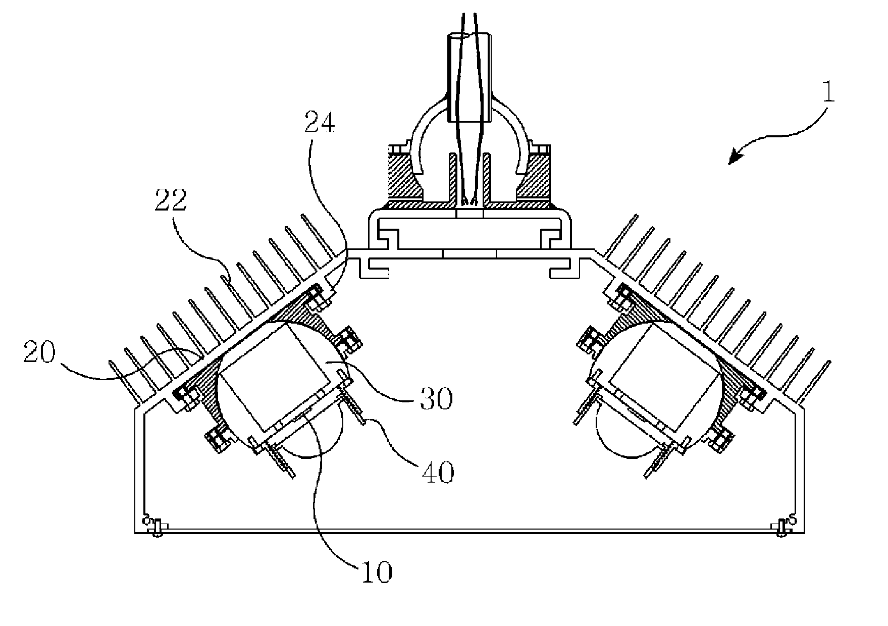
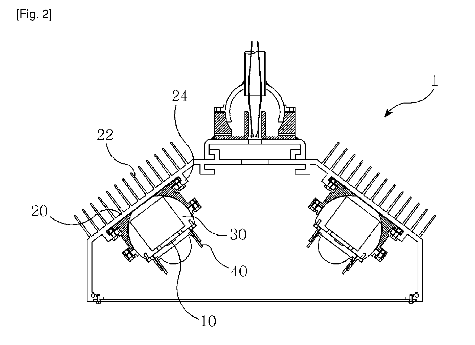
[0033]As shown in FIG. 4, the lighting direction adjuster 30 includes the spherical rotating body 32 and the receiving body 34 having the groove for receiving the spherical rotating body 34.
[0034]The receiving body 34 is formed with the spherical groove 35 for receiving the spherical rotating body 34. Upper and lower protruding portions 38 and 37 are formed at edge parts of upper and lower ends of the receiving body 34. The lower protruding portion 37 is fixed to the bracket 24 in the housing 1 by a bolt, and the upper protruding portion 38 is fixed to the cover plate 36 by a bolt.
[0035]The cover plate 36 functions to prevent the spherical rotating body 34 received in the groove 35 of the receiving body 34 from being separated from the groove 35. The cover plate 36 has an opening corresponding to an external shape of the spherical rotating body 32 so that the spherical rotating body 32 can be freely rotated. A Bolt hole is formed at an edge portion of the cover plate 36 so that the ...
second embodiment
[0049]As shown in FIG. 10, the lighting direction adjuster 30 has the same construction as that in the first embodiment. That is, as shown in FIGS. 11 and 12, the lens case 40 includes the lower lens case 42 and the upper lens case 44, and the upper lens case 44 is inserted into the lower lens case 42.
[0050]Herein, the lower lens case 42 is formed into a cylindrical shape of which upper and lower sides are opened. A flange 46 is formed at a lower end of the lower lens case 42 so as to be radially protruded to an inside of the lower lens case 42. The flange 46 is formed with a bolt hole by which the lens case 40 can be fixed to the upper surface 33 of the spherical rotating body 32 using the bolt.
[0051]The upper lens case 44 is formed into a cylindrical shape of which upper and lower sides are opened. A hollow portion 50 is formed at a lower end of the lower lens case 42 so as to be radially protruded to an inside of the upper lens case 44 in the form of an elliptical shape for recei...
PUM
 Abstract
Description
Claims
Application Information