Portable electronic device

a portable electronic device and flex cable technology, applied in the field of electronic devices, can solve the problems of reducing the service life increasing the cost and size of the portable electronic device, and complicating the structure and manufacture of the connection to the motherboard by flex cabl

Inactive Publication Date: 2011-03-31
HON HAI PRECISION IND CO LTD
View PDF1 Cites 33 Cited by
  • Summary
  • Abstract
  • Description
  • Claims
  • Application Information

AI Technical Summary

Problems solved by technology

However, the additional PCB increases cost and size of the portable electronic device,

Method used


Image

  • Portable electronic device
  • Portable electronic device
  • Portable electronic device

Examples


Embodiment Construction

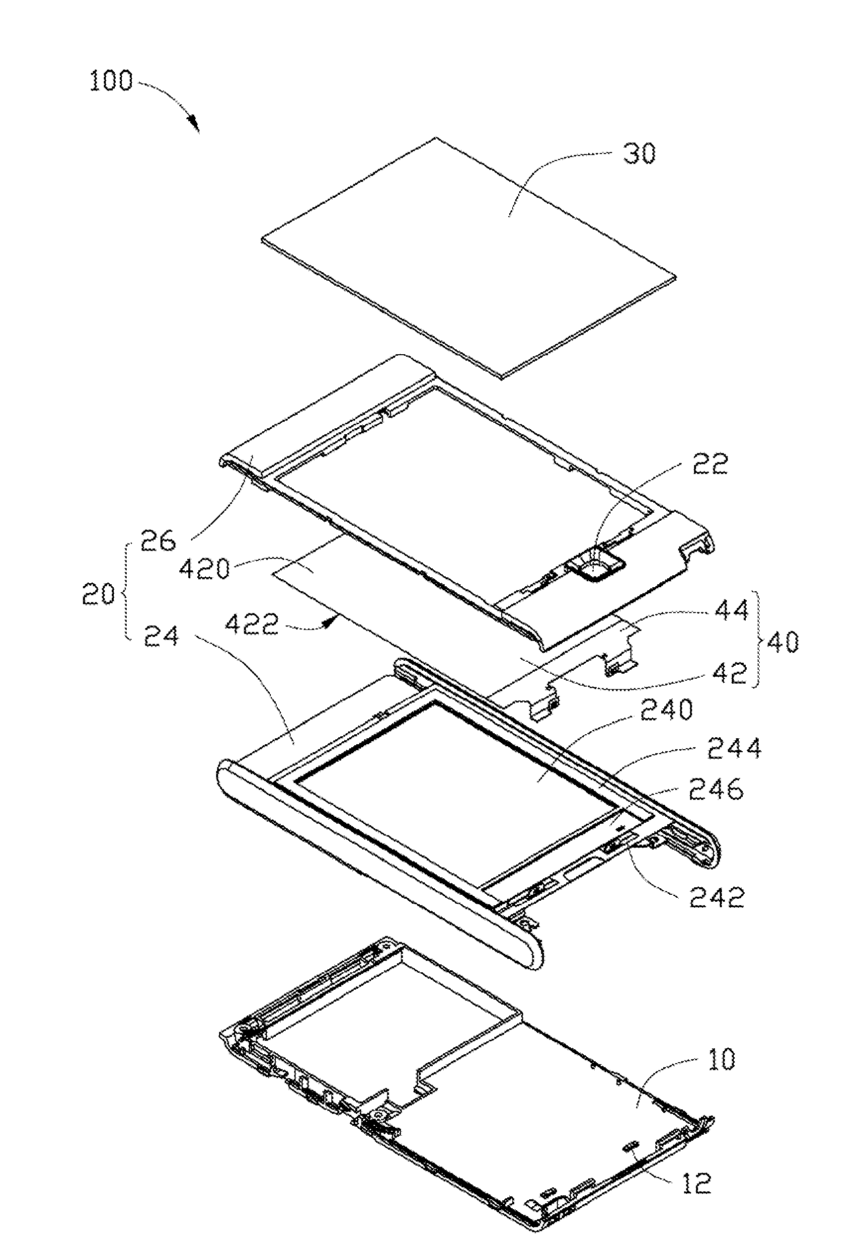
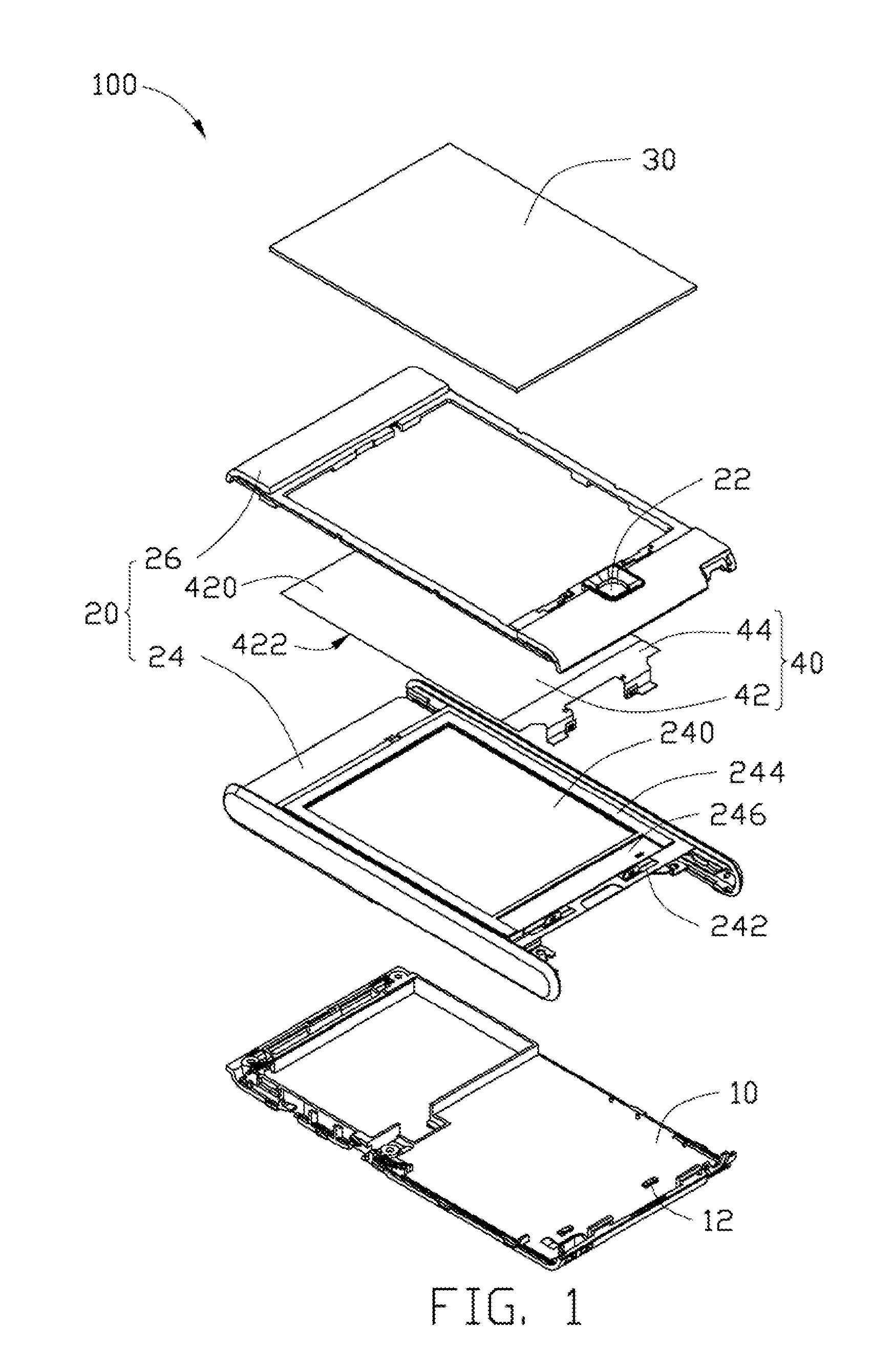
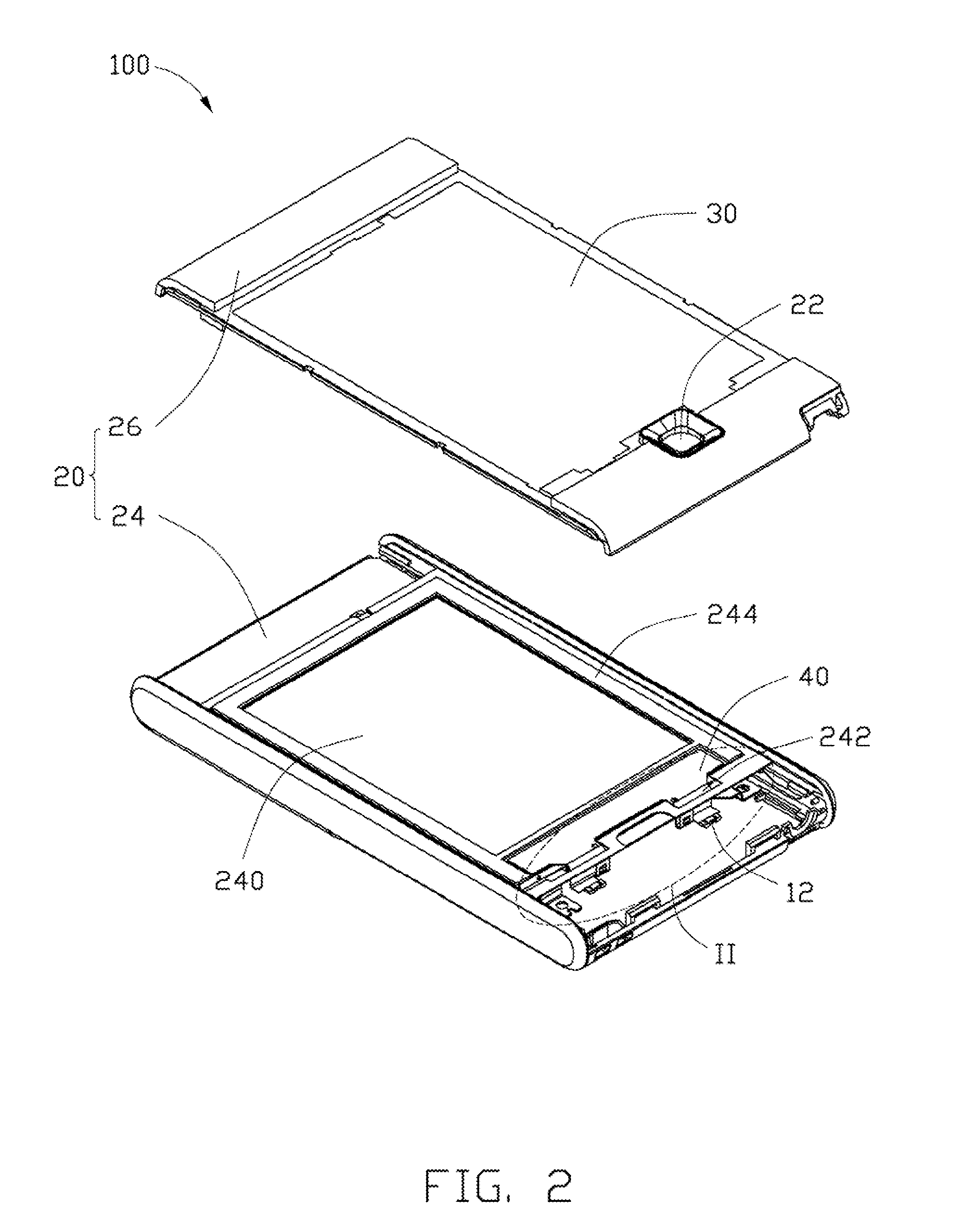
[0012]Referring to FIGS. 1 and 2, a portable electronic device 100 includes a motherboard 10, an outer shell 20 for covering the motherboard 10, and a display screen 30 embedded in the outer shell 20 and parallel to the motherboard 10. In this embodiment, the portable electronic device 100 is a mobile phone. A light guide component 40 is disposed between the motherboard 10 and the display screen 30.

[0013]The motherboard 10 includes two illuminators 12 electrically connected to a power supply (not shown) therein. In this embodiment, the illuminators 12 are light emitting diodes (LEDs).

[0014]The motherboard 10 further includes a control module (not shown) electrically connecting the illuminators 12 to a key 22 disposed on the outer shell 20. The control module is configured for turning on the illuminators 12 when a key 22 is pressed.

[0015]The outer shell 20 includes a holding frame 24 and a cover 26 attached to the holding frame 24. The holding frame 24 defines a first receiving openi...


PUM


Abstract

A portable electronic device includes a motherboard including at least one illuminator disposed thereon, a display screen parallel to the motherboard, and a light guide component disposed between the illuminator and the display screen. The light guide component includes a main body attached to a bottom surface of the display screen, and at least one foot portion extending from an edge of the main body corresponding to the at least one illuminator. The main body includes a light output surface facing the display screen. Each foot portion includes a distal end surface facing the illuminator to receive light emitted therefrom.

Description

BACKGROUND[0001]1. Technical Field[0002]The present disclosure relates to electronic devices and, particularly, to a portable electronic device.[0003]2. Description of Related Art[0004]A conventional portable electronic device, such as a mobile phone, often includes a display screen, a motherboard, and a number of keys electrically connected to the motherboard. Furthermore, a number of light emitting diodes (LEDs) may also be positioned beside the display screen, to provide light in the absence of ambient lighting. The LEDs are embedded in an additional printed circuit board (PCB), separate from the motherboard. Conventionally, the PCB is positioned parallel or perpendicular to the motherboard and electrically connected thereto by flex cables. The LEDs may be electrically connected to the keys via circuitry on the PCB and the flex cables. Pressure on a key causes the LEDs to emit light to illuminate the display screen. However, the additional PCB increases cost and size of the porta...

Claims


Application Information

Patent Timeline
IPC IPC(8): F21V7/04
CPCH04M1/22H04M1/0266
Inventor CHIANG, CHIA-CHIN
Owner HON HAI PRECISION IND CO LTD
Why Eureka
Try Eureka