Transmission device

Active Publication Date: 2017-10-10
AISIN AW CO LTD
View PDF29 Cites 0 Cited by
  • Summary
  • Abstract
  • Description
  • Claims
  • Application Information

AI Technical Summary

Benefits of technology

[0003]The compound planetary gear mechanism included in the conventional transmission device described above transmits power transmitted to the input element to the first and the second output members at an increased speed when the fixable element is non-rotatably held stationary by the brake. As a result, in the transmission device described above, the maximum rotational speeds of components, such as clutch hubs and clutch

Problems solved by technology

Trying to secure strength of the components subjected to such high centrifugal forces causes

Method used


Image

  • Transmission device
  • Transmission device
  • Transmission device

Examples


Embodiment Construction

[0037]The following will describe modes for carrying out the present disclosure with reference to the drawings.

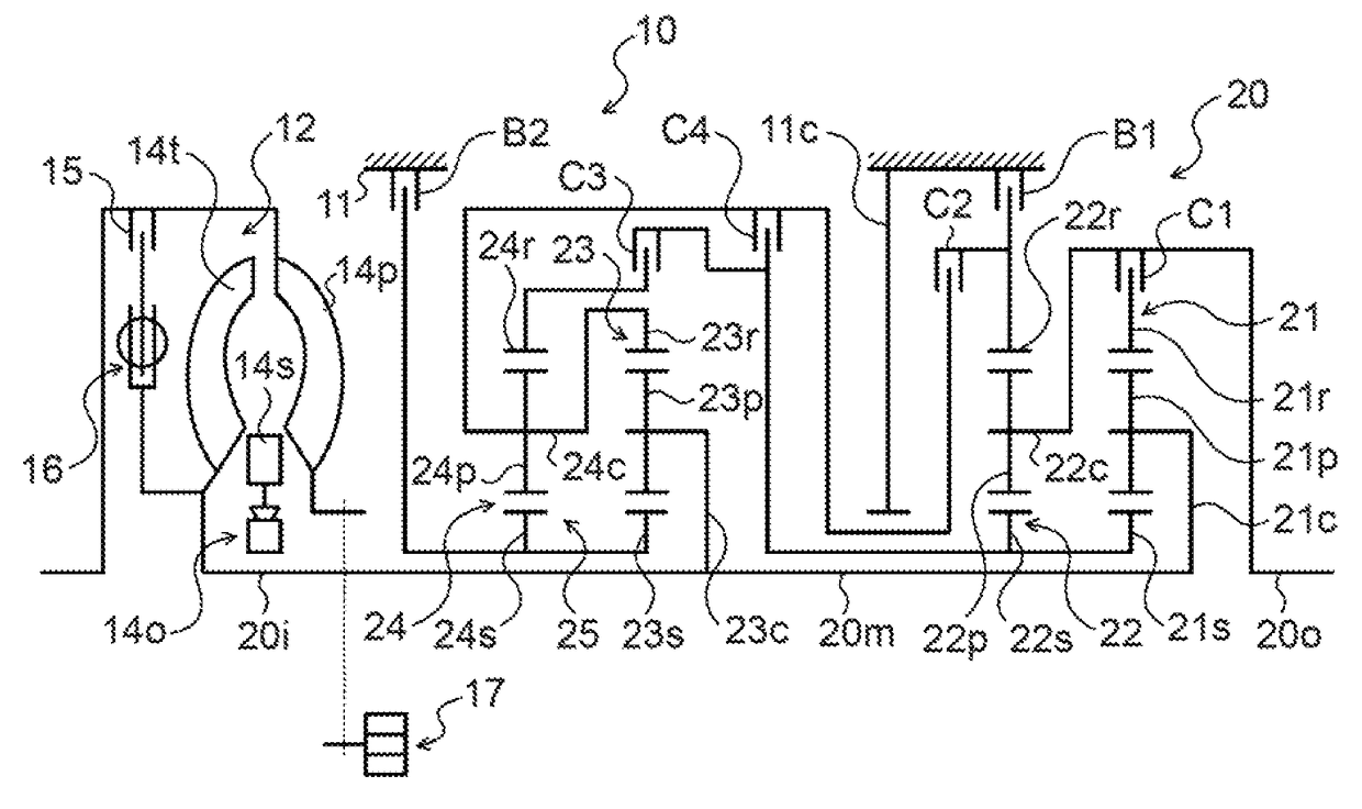
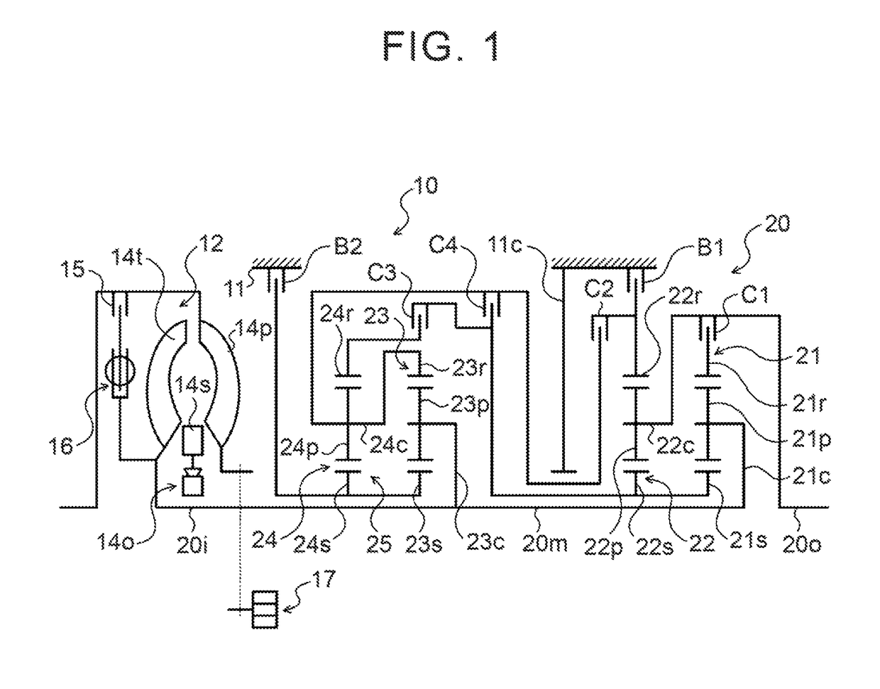
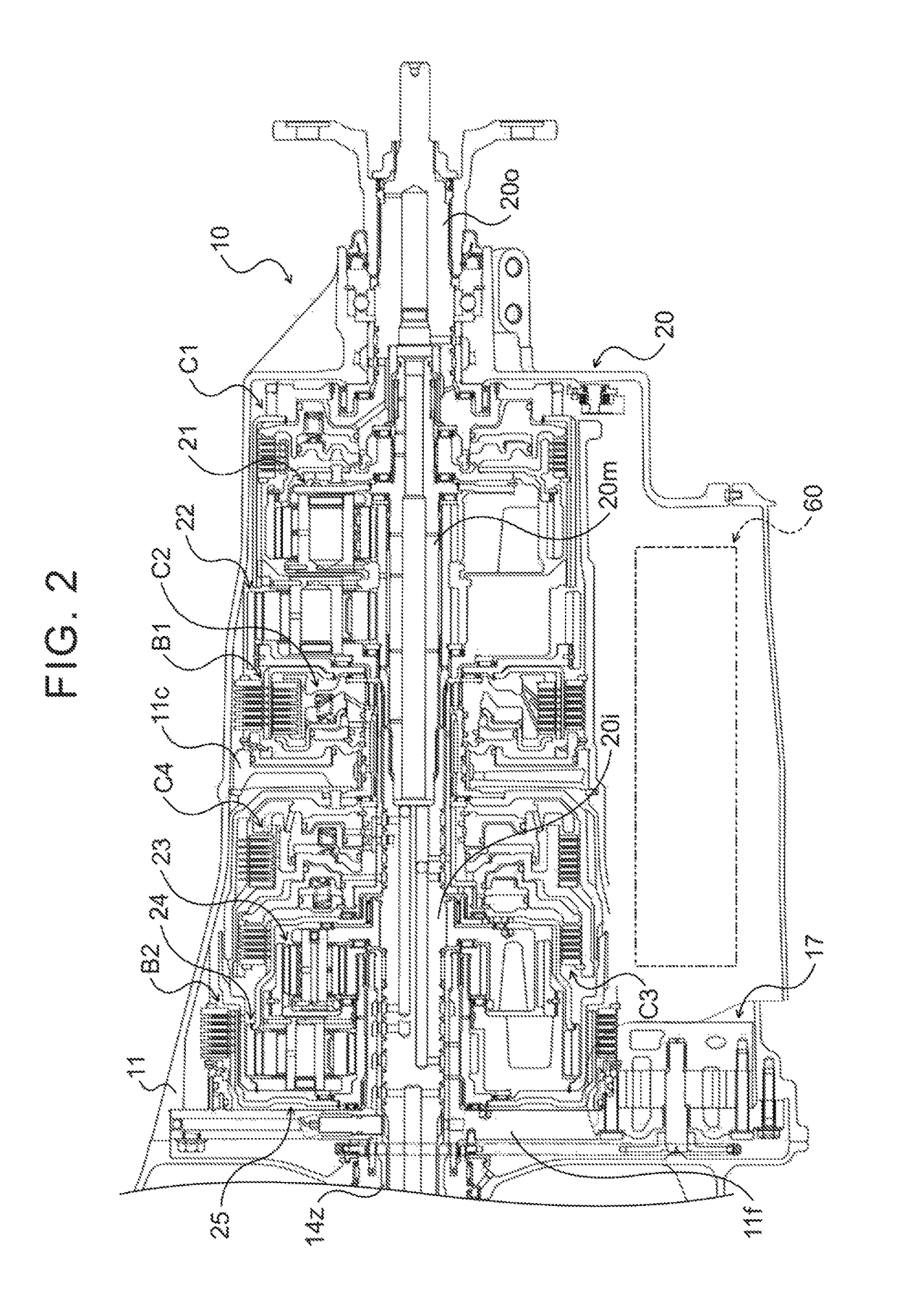
[0038]FIG. 1 is a schematic structure diagram of a power transmission device 10 including an automatic transmission 20 serving as a transmission device according to an embodiment of the present disclosure. FIG. 2 is a sectional view showing the power transmission device 10. The power transmission device 10 shown in FIGS. 1 and 2 is connected to a crankshaft of an engine (internal combustion engine) and / or a rotor of an electric motor (not shown) serving as a driving source longitudinally mounted on the front of a rear-wheel-drive vehicle, and can transmit power (torque) from the engine or the like to left and right rear wheels (driving wheels) (not shown). As shown in FIG. 1, the power transmission device 10 includes, for example, a transmission case (stationary member) 11, a starting device (fluid transmission apparatus) 12, and an oil pump 17, in addition to the automatic...


PUM


Abstract

A transmission device, wherein the compound planetary gear mechanism increases the speed of the power transmitted to the input element and transmits the resultant power to the first and the second output elements when the fixable element is non-rotatably held stationary by the first brake; and the first and the second clutches are disposed on a side closer in the axial direction to the compound planetary gear mechanism than the first and the second planetary gear mechanisms.

Description

BACKGROUND[0001]The present disclosure relates to a transmission device that changes a speed of power transmitted from a motor of a vehicle to an input shaft and transmits the resultant power to an output shaft.[0002]Conventionally, a transmission device that includes two single-pinion type planetary gears, what is called a Simpson compound planetary gear mechanism, four clutches, and two brakes are known as a transmission device of such a type. (see U.S. Pat. No. 8,202,190, for example). The compound planetary gear mechanism included in such a transmission device includes an input element connected to an input shaft, a fixable element selectively non-rotatably held stationary by a brake, and first and second output elements. The first output element is selectively connected to another rotational element by a first clutch, and the second output element is selectively connected to yet another rotational element by a second clutch.SUMMARY[0003]The compound planetary gear mechanism inc...

Claims


Application Information

Patent Timeline
IPC IPC(8): F16H3/62F16H61/02F16H3/66F16D25/0638F16H37/08F16D25/10F16H61/00
CPCF16H3/663F16D25/0638F16H3/66F16H3/666F16H37/0813F16H61/0265F16H2200/2046F16D25/10F16H2061/0046F16H2200/0069F16H2200/2012F16H2200/2023
Inventor SUGIURA, NOBUTADAMORIMOTO, TAKASHIAOKI, TOSHIHIKOKATO, HIROSHIKASUYA, SATORUOTAKE, MASAHIROMURAKAMI, MASANORINAKAJIMA, TAKUYA
Owner AISIN AW CO LTD
Why Eureka
Try Eureka